Video sequencer
Winter 2024 – Early 2025
In early 2024 I built the video console, and since then I've had the chance to use it a lot:
- I made a music video for Rosie Tucker
- I've installed it at Gray Area's Bring Your Own Beamer (BYOB) pop up art show twice
- I showed it at the Dogbotic Audio Carnival at 924 Gilman
- I used it for audience-driven visuals in a recording of a new hardware techno live set.
It's very fun and engaging! Audiences always seem to have a great time playing with it too. However, I had a few things on my wish list for improvements.
- It has a lot of analog inputs that are noisy and glitchy due to weird cross-talk with all the spaghetti wiring under the hood (it's kind of charming, but also makes things a little... jumpy on screen)
- I wanted to make more complex patterns with layers of shapes stacked on top of each other, and the layout of physical controls on the video console didn't feel quite right for that
- I wanted something a little more robust and portable
- I wanted to add a step sequencer so I could control how the patterns evolve over time (and maybe even tempo sync it to my drum machine?)
Overall, I wanted to add more depth and complexity to the kinds of patterns it can create. Maybe that would mean sacrificing a bit of the "walk up and fiddle with it" approachability, but maybe it would be compelling enough to be worth a bit of effort to understand. So I made the Video Sequencer!
Here's a video of it installed at Gray Area's monthly-ish BYOB event! This thing was a real crowd pleaser I think — it has ways to quickly randomize or shake up your composition, and I think that made it really fast and fun to experiment with.
I started this project during Art Month, and it turned out to be trickier than I anticipated! I'm glad it's finished though, and I love the way it came out!
Design goals
Thinking about my wish list, I wrote down a few parameters I wanted to work within:
- Mostly digital inputs (buttons and encoders, rather than sliders and rotary potentiometers) to try to avoid noise and jumpiness
- Overlapping visual layers to make more elaborate designs
- Some kind of sequencer with tempo control to make patterns change over time
- Modular design, so it's easy to change the layout or specific input devices as I prototype and experiment
- Robust and sleek enclosure (the last one was... a bit messy)
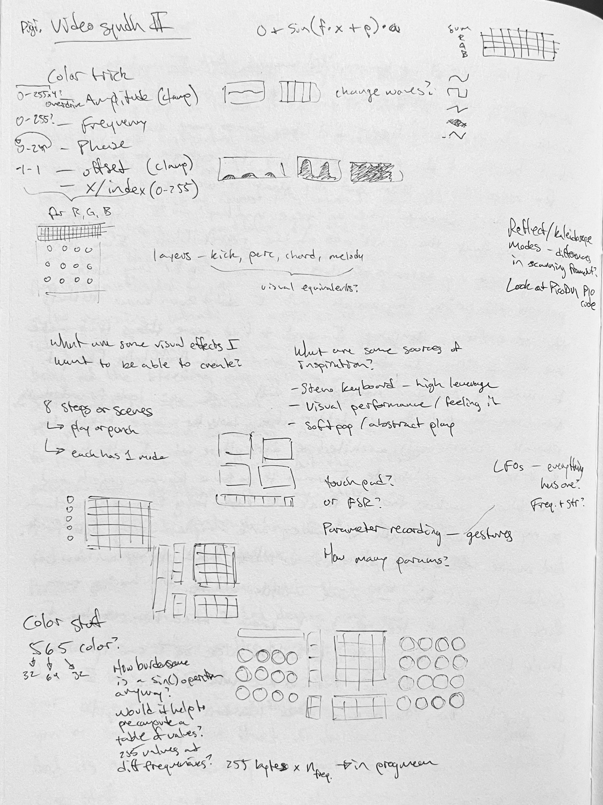
Generating color palettes
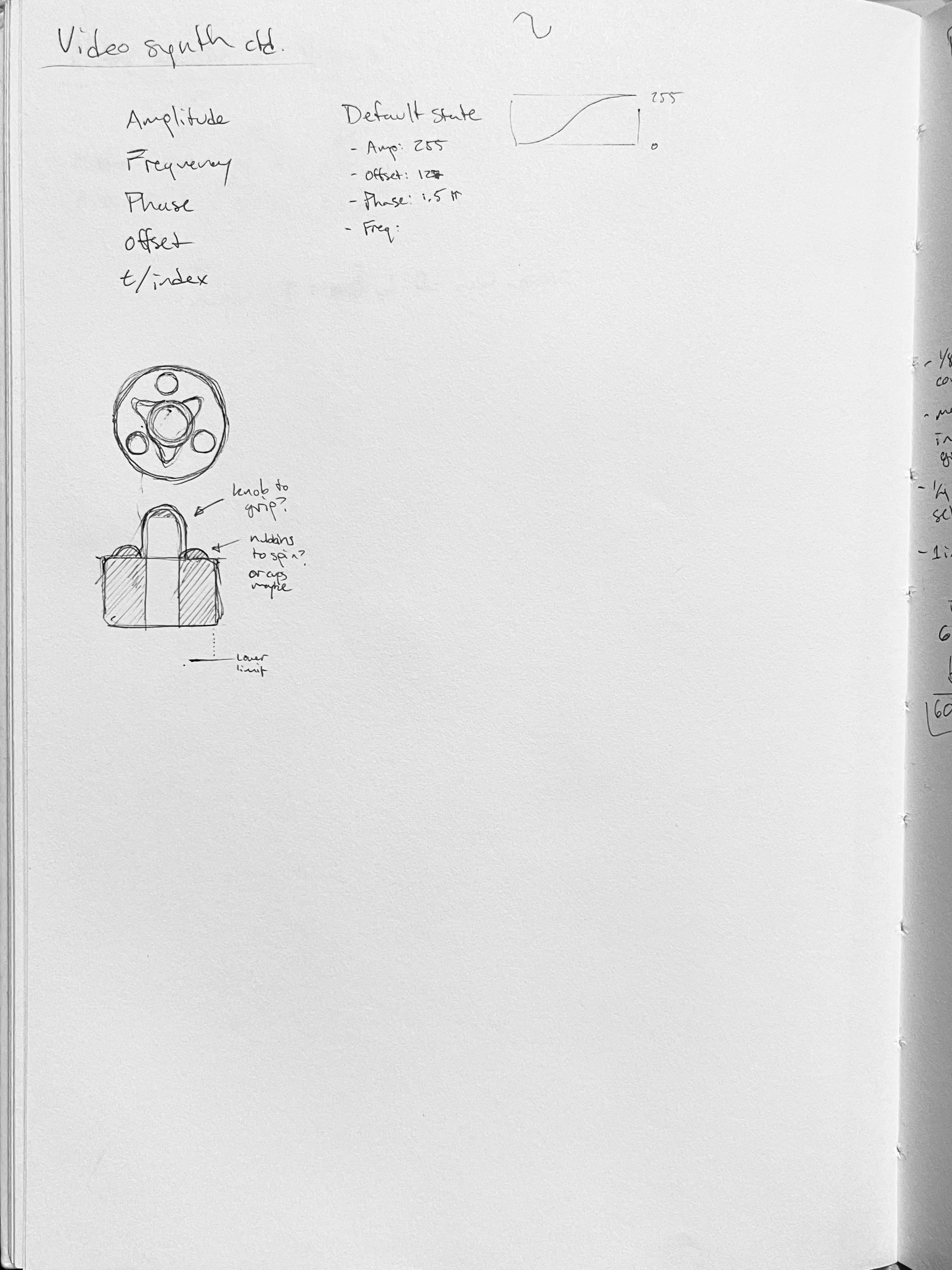
The thing that really motivated me to start working on this project was this fascinating video by Inigo Quilez on Tiktok, where he shares a method for generating fun color palettes. The basic technique is to sample a separate sine wave for each of the red, green, and blue channels of your color palette, and control the evolution of the colors with the amplitude, frequency, phase, and offset of each sine wave.
To learn more, check out the original writeup about the Sinebow technique by Jim Bumgardner and this further analysis and comparison with similar techniques by Mike Bostock.
In the Video Console, I tried generating color palettes by picking three RGB colors and using them as the beginning, middle, and end of the palette and just averaging / interpolating between them. There was a helpful "directness" in that technique, though the colors often ended up muddy, and there's really only so much you can do with a three-point gradient.
Prototyping color palettes
I wanted to experiment with this technique myself, so I put together a quick Observable notebook (embedded below) to see what it would be like to actually use those controls to craft a color palette.
- At the top are three groupings of controls for the red, green, and blue channels of the palette. Frankly it makes a lot more sense if you just play with it a bit, but here's a quick description of what each control does.
- Amplitude: the magnitude of the variation in the value
- Frequency: the speed with which the value changes over the range of the palette
- Phase: the "start point" for the oscillation
- Offset: a fixed positive or negative bias in the value
- Below that is a chart that shows the red, green, and blue sine waves, which show how each component of the RGB color changes as you move throughout the color palette
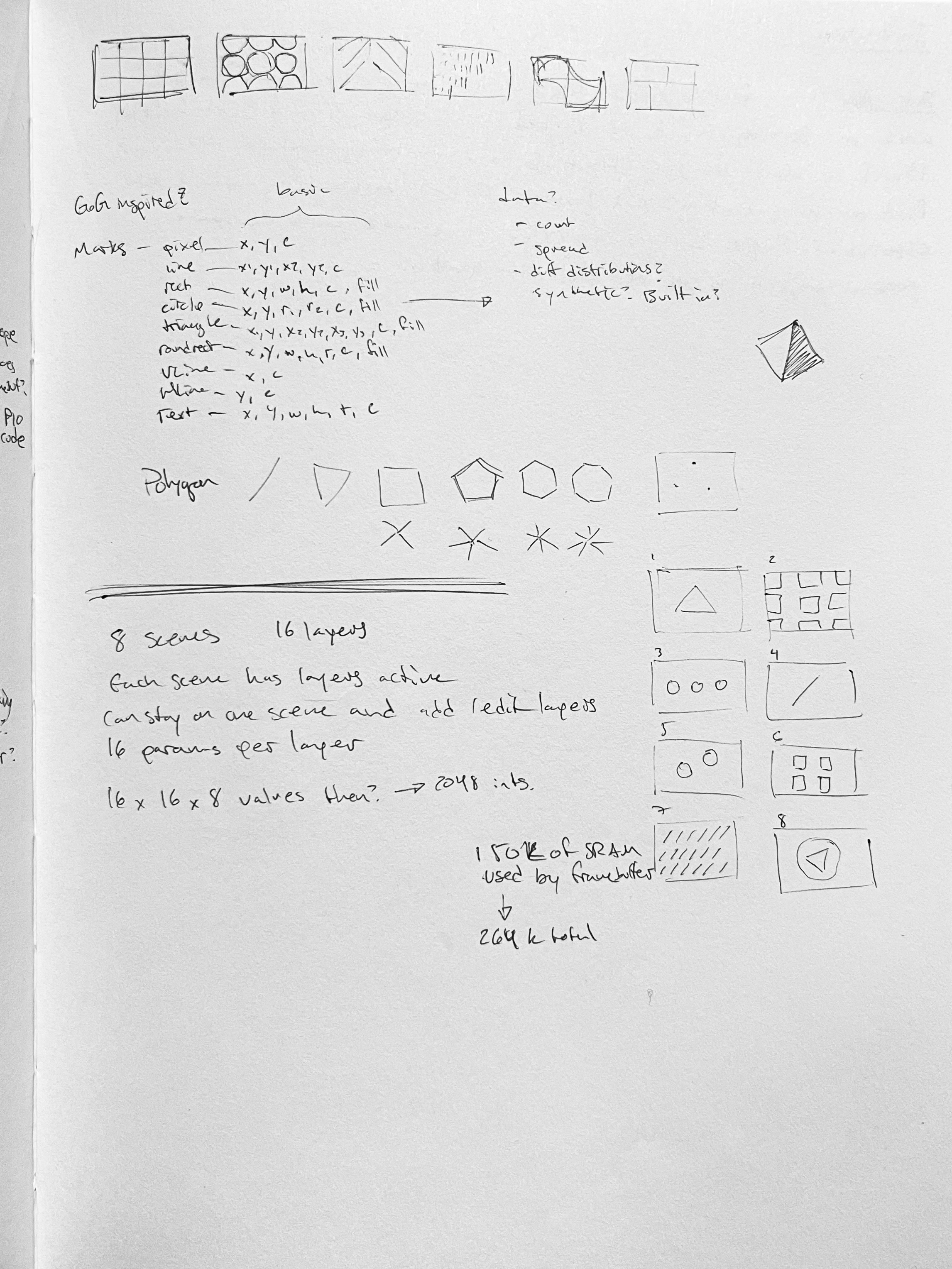
- Since I'm using the same RP2040 microcontroller as in the Video Console it has some of the same constraints on the nature of the palette
- There are 256 "slots" in the palette to fill
- Each "slot" can hold a single 16-bit color, encoded as an RGB565 color — of the 65536 colors in that color space, you get to pick which 256 you want to use!
- This means that there are 5 bits to represent red, 6 bits to represent green (because our eyes are more sensitive to shades of green), and 5 bits to represent blue
- The extra bit of fidelity in the green channel means that there are 64 levels of green-ness instead of 32 for red-ness and blue-ness, so that sine wave is a little less blocky than the other two
- Below that sinewave chart is a strip showing all 256 colors in the palette
- Then we have a depiction of the full color space, and dots showing which 256 colors from the 65536 possible colors you've chosen
- Below that is a little sample art that applies the palette to some shapes
- Finally theres a 8x4 grid of color swatches — this is an experiment in summarizing the palette configuration with a grid of 32 LEDs that I wanted to install in the enclosure. More about that later though!
Controls
After playing with this, I decided it was fun and compelling enough to give it a shot in the video synth. It's a little hard to explain to others, but at this point I decided it was what I wanted in a video synth and that's enough :)
The important part of that notebook is the sampleColor() function, which takes a value i in the range 0-255. I implemented a very similar function in the palette control code in my arduino project!
let sampleColor = function (i) {
  // Apply the variables in the formula mentioned in the video
  // Math.sin() produces values from -1 to 1
  // A default offset of 0.5 and amplitude of 0.5 shift it to a range of 0-1
  // But the user could choose to shift / amplify outside that range
  let r =
    red.offset +
    red.amplitude * Math.sin((red.frequency / 8) * i + red.phase * Math.PI * 2);
  let g =
    green.offset +
    green.amplitude *
      Math.sin((green.frequency / 8) * i + green.phase * Math.PI * 2);
  let b =
    blue.offset +
    blue.amplitude *
      Math.sin((blue.frequency / 8) * i + blue.phase * Math.PI * 2);

  // Restrict each channel to the range 0-255,
  // Limit the bit depth according to the 5-6-5 scheme,
  // Return the color array
  return [
    clamp(Math.round(r * 255) & ~0b111, 0, 255),
    clamp(Math.round(g * 255) & ~0b11, 0, 255),
    clamp(Math.round(b * 255) & ~0b111, 0, 255)
  ];
}
Initial concepts
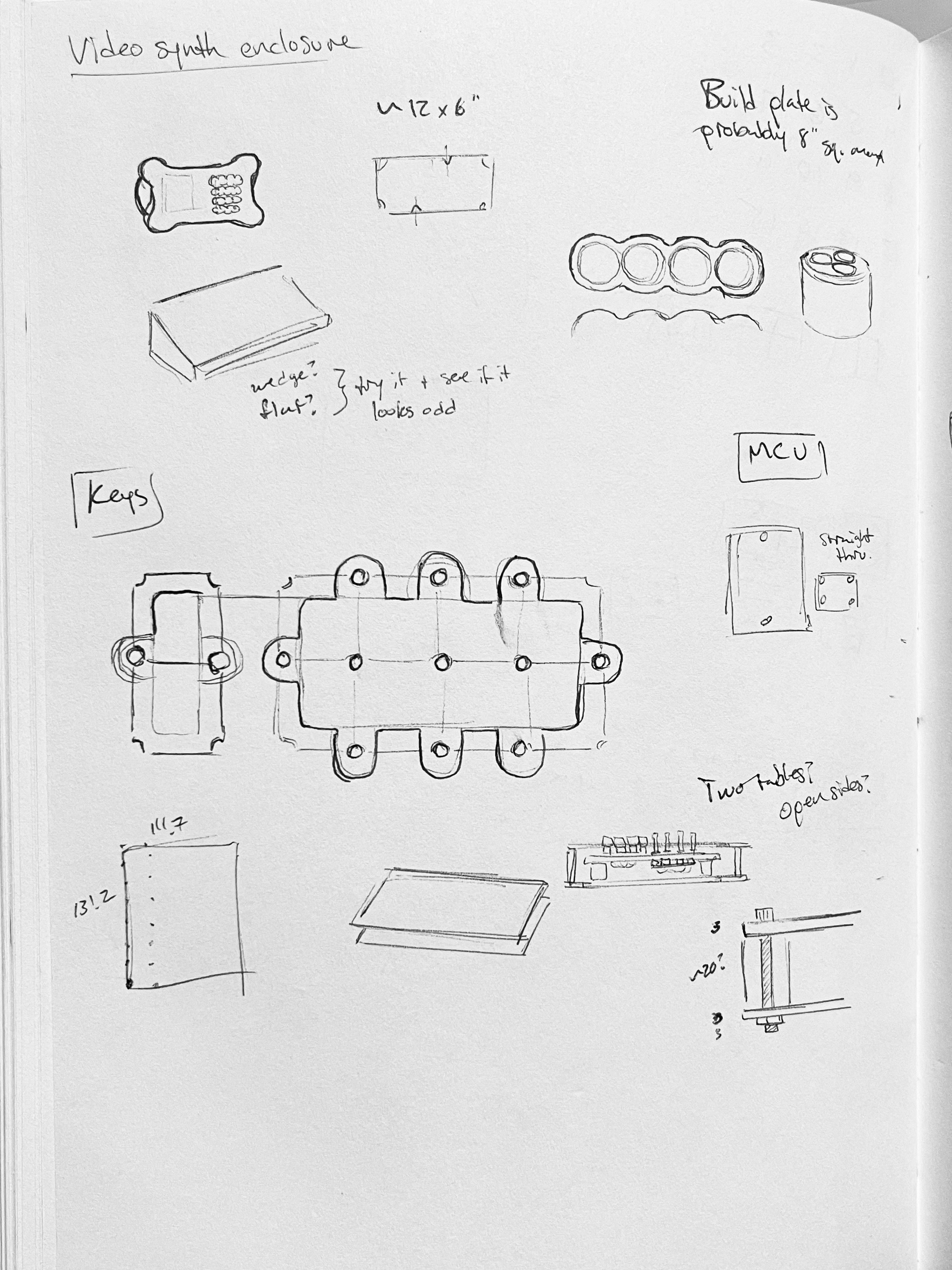
Prototype in hand, I started sketching out a few ideas for the interface, the patterns, and circuit considerations. I also started browsing around Adafruit's inventory of input devices and components.
Ultimately I settled on a few components that seemed flexible, engaging, and useful:
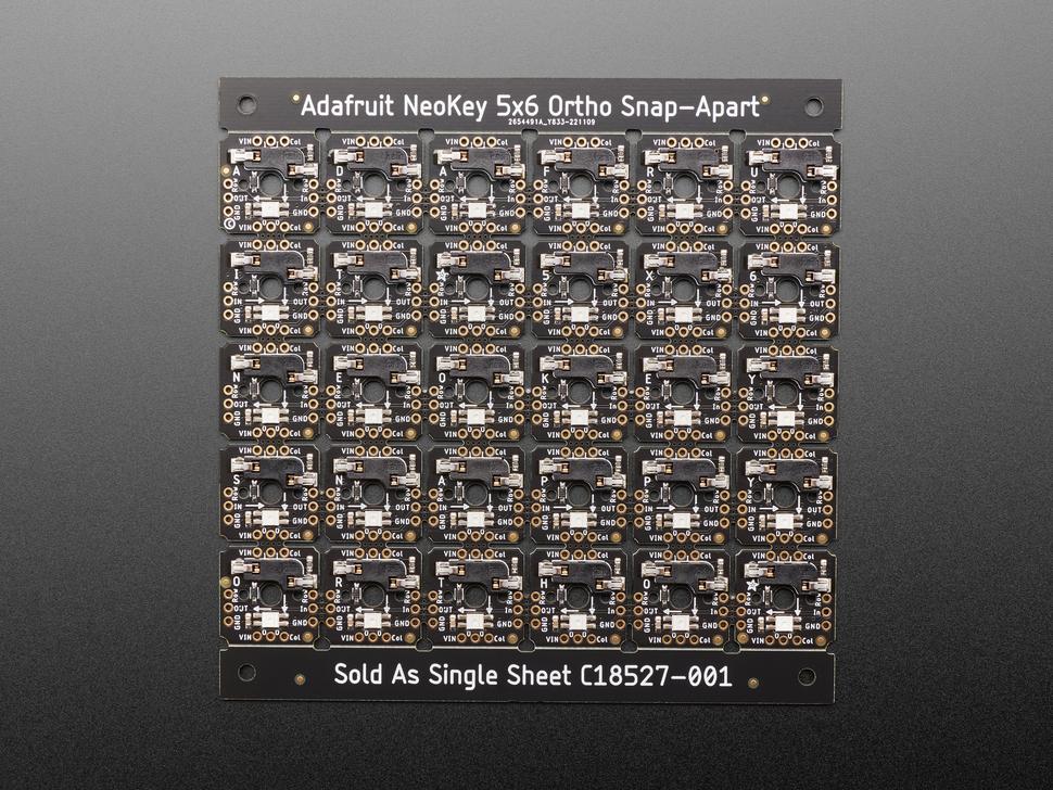
- This board helps you wire up a custom mechanical keyboard!
- Each key tile has a connector for a Cherry MX switch and an LED that can illuminate the keycap
- You can snap the grid apart into sections if you want smaller arrays of keys
- It's wired up so you can scan through the array with just one pin for each row and column (and they have a convenient library for doing this)
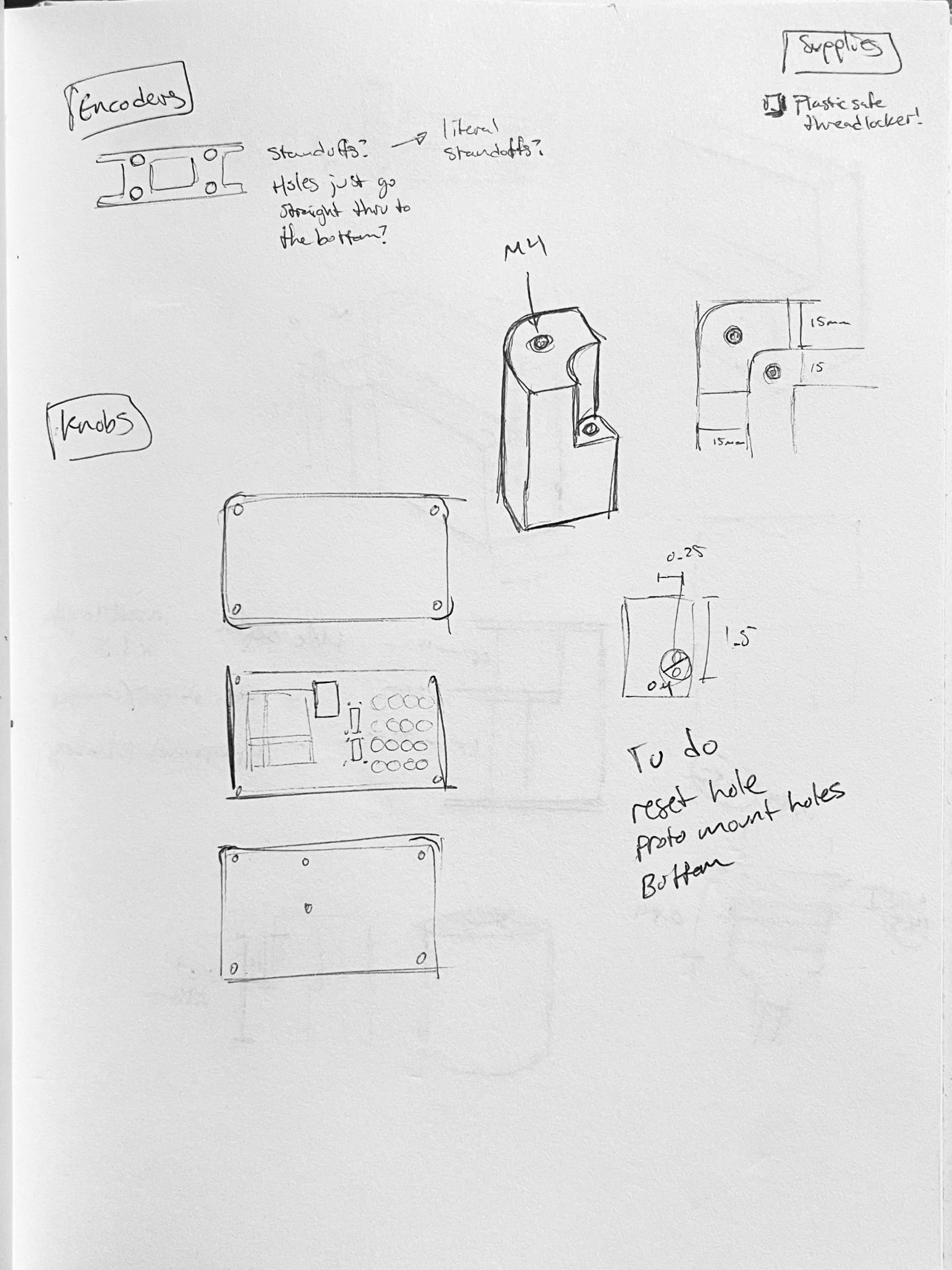
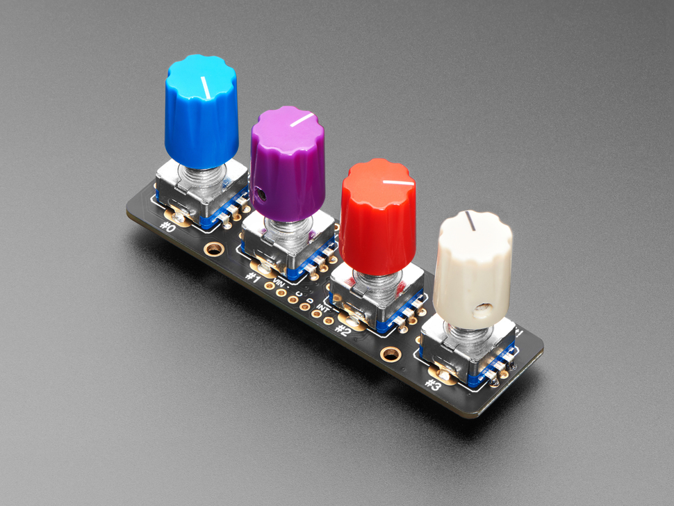
- Rotary encoders are fun, but each one requires monitoring two signal pins for changes
- This breakout board has a little microcontroller on it called a Seesaw that does that for you, keeps track of the position, and reports values over I2C!
- It can keep track of 4 encoders, and you can daisy-chain up to 8 of these things together on a single I2C bus
- My only complaint is that the encoders are spaced 0.75" apart, which feels a bit tight IMO
- This board has a grid of 32 LEDs arranged in a 4x8 grid
- I figured it would be perfect for some user feedback about the status of the color palette and encoder values
- As seen in my prototype notebook above, I tried summarizing the color palette by showing 8 samples each for the red, green, and blue channels, then 8 samples of the combined palette
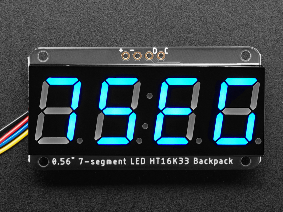
- I got four of these because I figured they'd be useful for showing a line of text indicating what mode you're in, etc
- I wound up not using them for a few reasons:
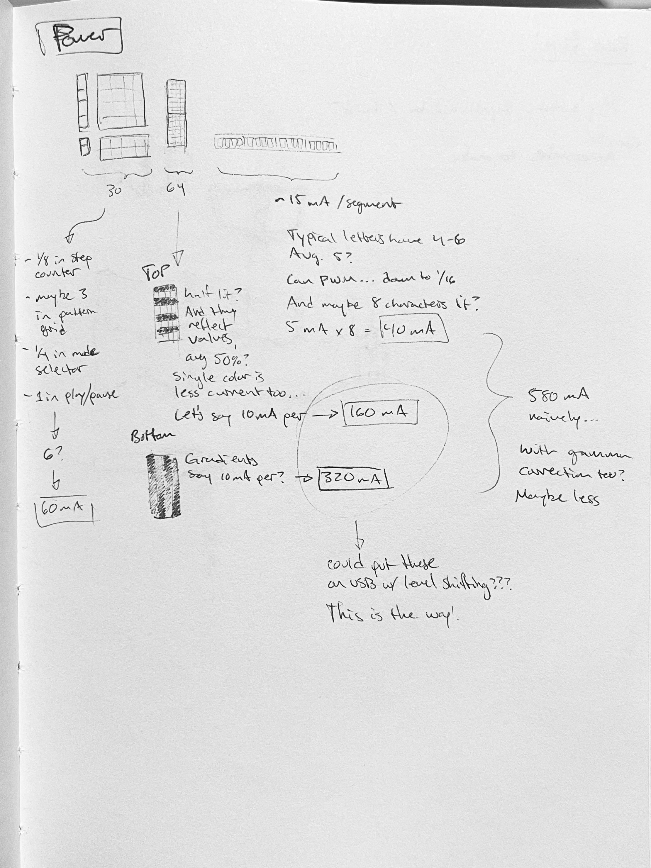
- The microcontroller was already stressin' enough controlling LEDs and running the video (I already had to limit the LEDs to update only about once a second because it was causing the video to stutter)
- Also I thought it might distract and keep users' eyes on the device instead of on the output display where they should be
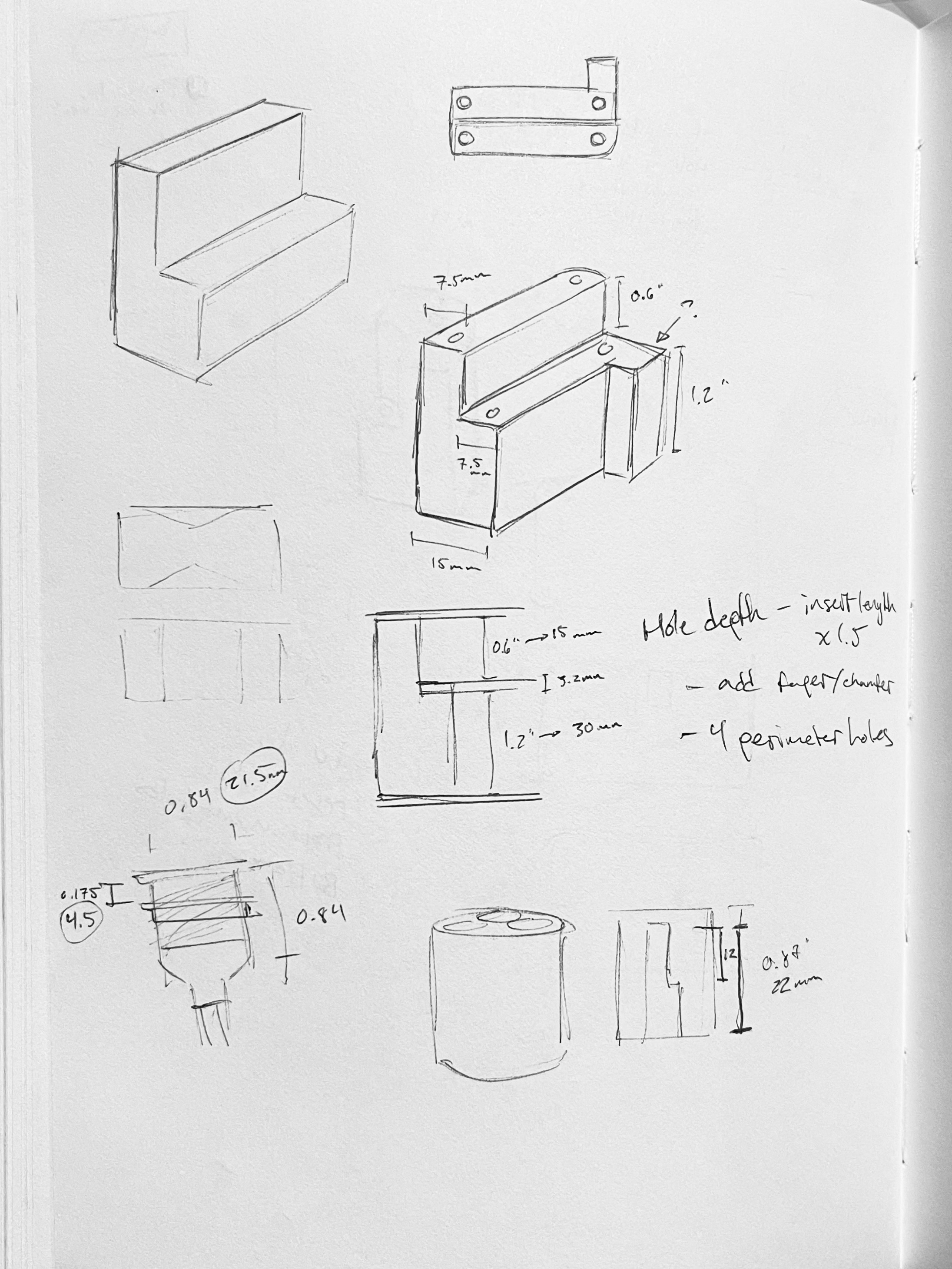
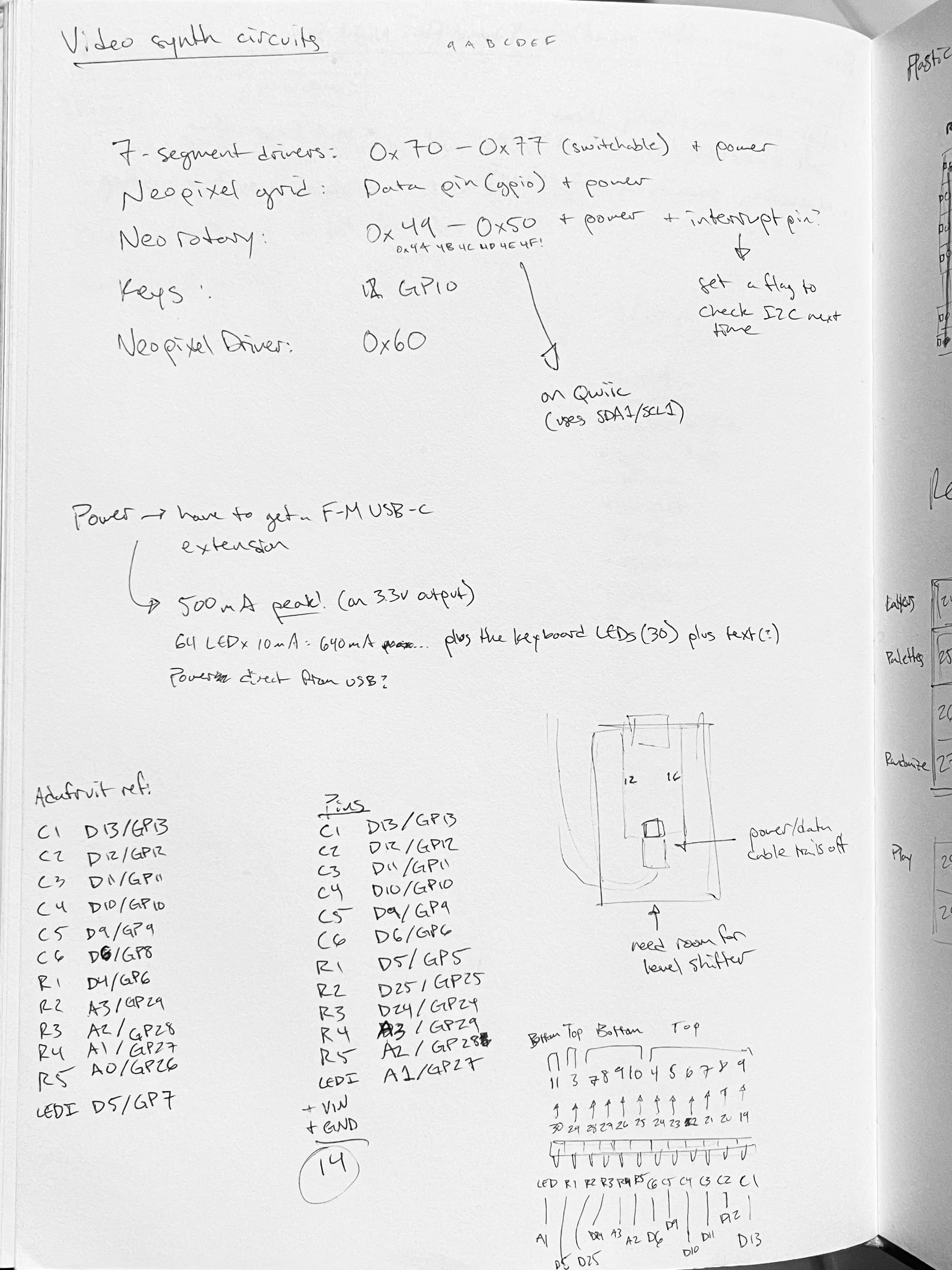
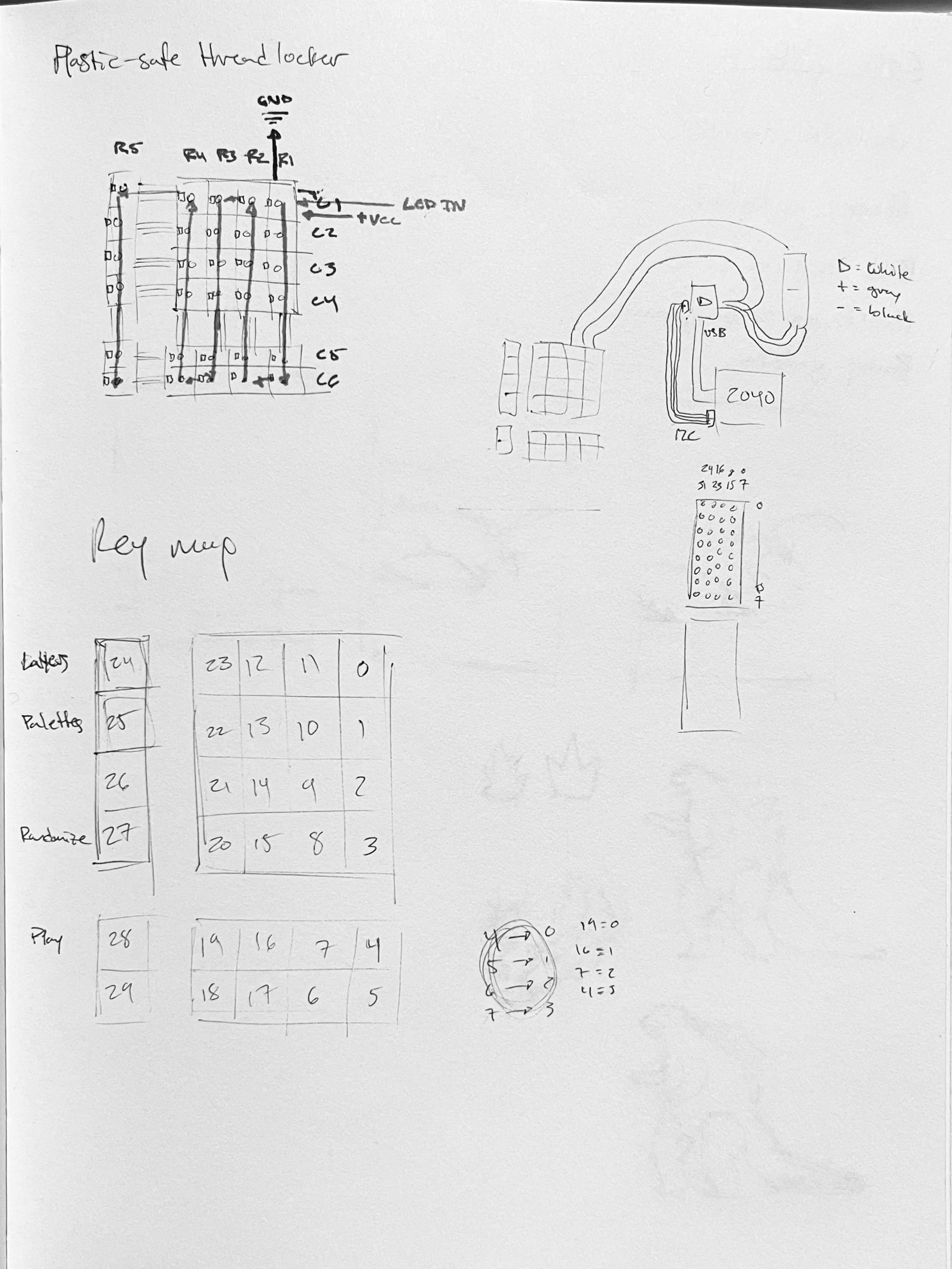
Circuits
Enclosure