Analog Video Synth
Summer 2021
In August 2021, I took an amazing creative electronics workshop by the folk at Dogbotic Labs. It was about building analog video synthesis circuits — as in, circuits that hook up to a cathode ray tube TV and output an NTSC video signal on a composite video jack.
Over the course of 10 weeks we hand built a "sync generator" — the basic circuit that can interface with a CRT TV and create a valid NTSC video signal. This requires creating carefully tuned timing circuits that send out pulses to initiate a new frame (or "VSYNC") and draw scan down the individual lines ("HSYNC"). You can use those to signals to create patterns of brightness that make a black and white picture. At the end of the workshop we used those signals to drive an AD725 color encoder that can take three brightness signals and use them as RGB input to make a full color image.
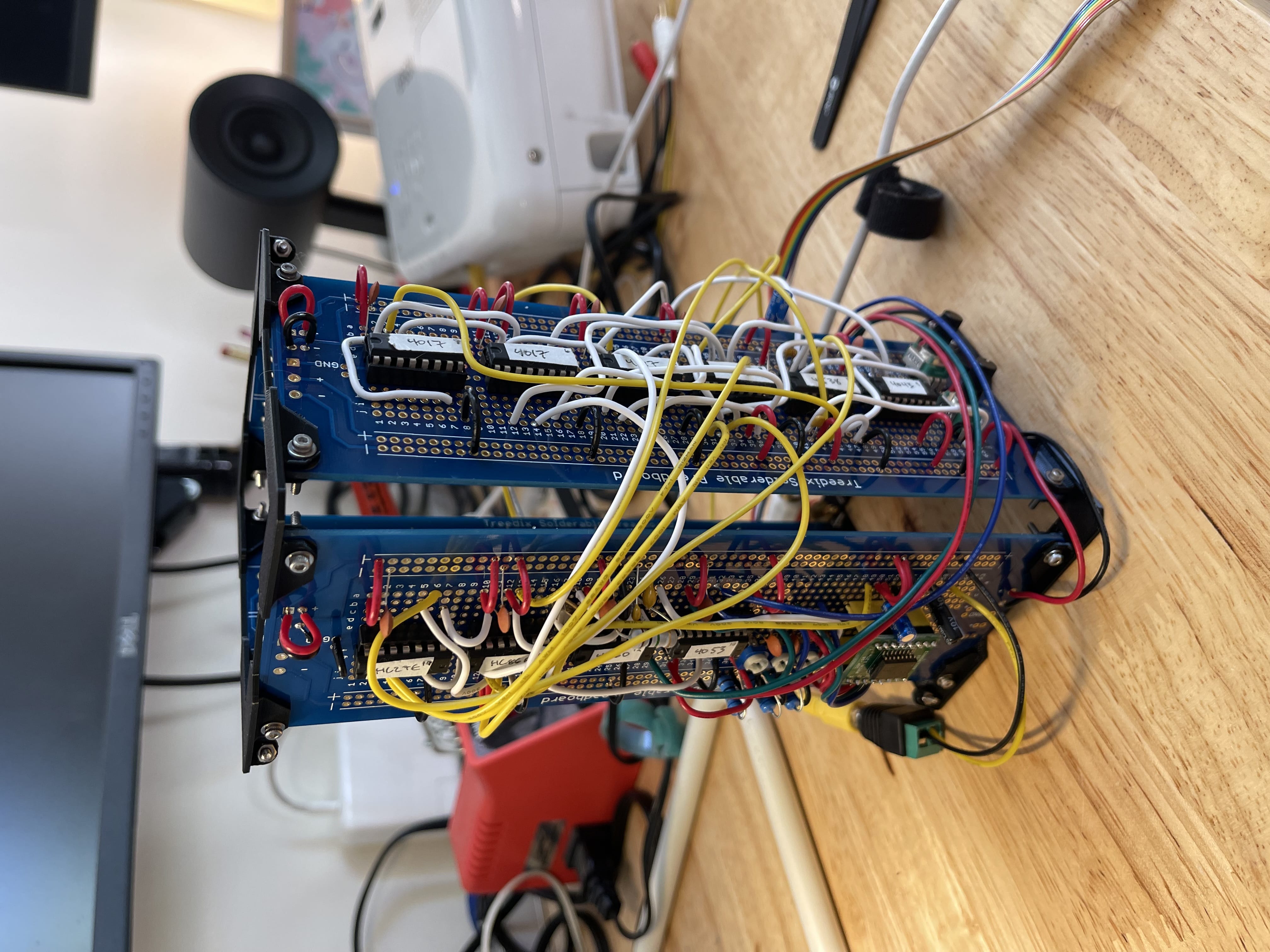
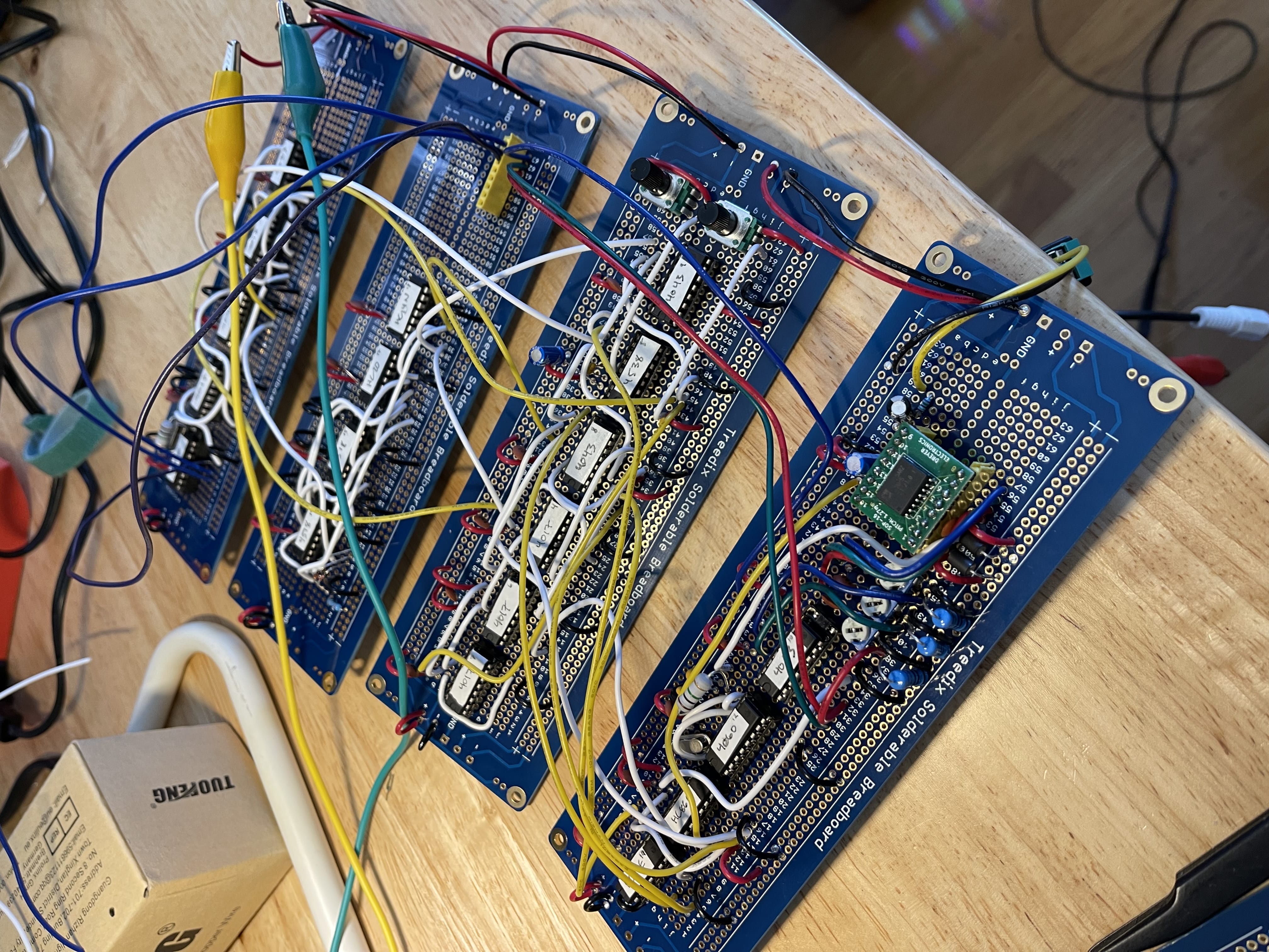
I really loved the process of carefully hand-building a circuit to perform such a mysterious process, so when I finally finished it, I 3d printed a set of brackets to hold the perma-proto boards upright in a sort of tower to show off my work.
The circuit
I didn't design the sync circuit, so I won't share the schematic here, but it's the work of Sean Hallowell. The design is quite elegant! It uses really simple building blocks in what feels like an intricate electric clockwork mechanism to recreate this crazy timing signal:
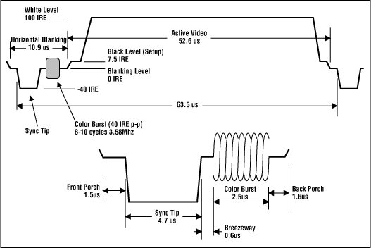
The "horizontal blanking" interval occurs before every line of a video frame. For a full explanation of how this analog synth works, it's worth taking a class. But let's look at a few examples I recorded while I was building this circuit to get a feel for how it works!
Basic bars
The circuit can tell you when a new frame starts, and when a new line in that frame starts
You can use those to generate a simple pattern of brightness information for that line of video
For example, if you give it a square wave, that's a repeating pattern of high and low voltage (so... high and low brightness). On a line of video on-screen, that would look like strips white and black. And many of those rows together would form vertical columns!
If you have a square wave that's really slow — slower than the drawing period of a single row of video, then you would have a few rows of high brightness, then a few rows of low brightness… which would look like horizontal rows of white and black!
Here, I'm using push buttons to momentarily send square waves of different frequencies to the output... so it's kinda playable! When I press multiple buttons at the same time they mix and glitch out a bit because they're not blended properly yet.
The sound that you're hearing is actually the video signal — you can hear that columns are faster square waves (higher pitch), and rows are slow square waves (lower pitch). The audio is actually pitched down a few octaves so you can hear it more easily.
Fancier patterns
This circuit switches between a bunch of different patterns!
There are a bunch of interesting techniques on display here. That pattern with the grid of six rectangles filled with swirling lines is my favorite. The swirling pattern is formed by a square wave that isn't perfectly synced to the clock. The frequency varies a bit, making the alternating white and black segments of the scan lines vary in length, which slightly offsets the stripes between rows.
That pattern is then masked out into the grid shape by white rows and columns. Internally, this uses a digital logic switch to flip back and forth between two incoming signals: the swirling lines and solid white.
The triangle / sawtooth shape is fun too — that uses a counter to increase the delay before switching from white to black until it reaches a threshold and resets.
The blinking inverted column pattern uses an actual digital inverter to flip to the opposite color when the scanline reaches that horizontal segment of the screen
Basic colors
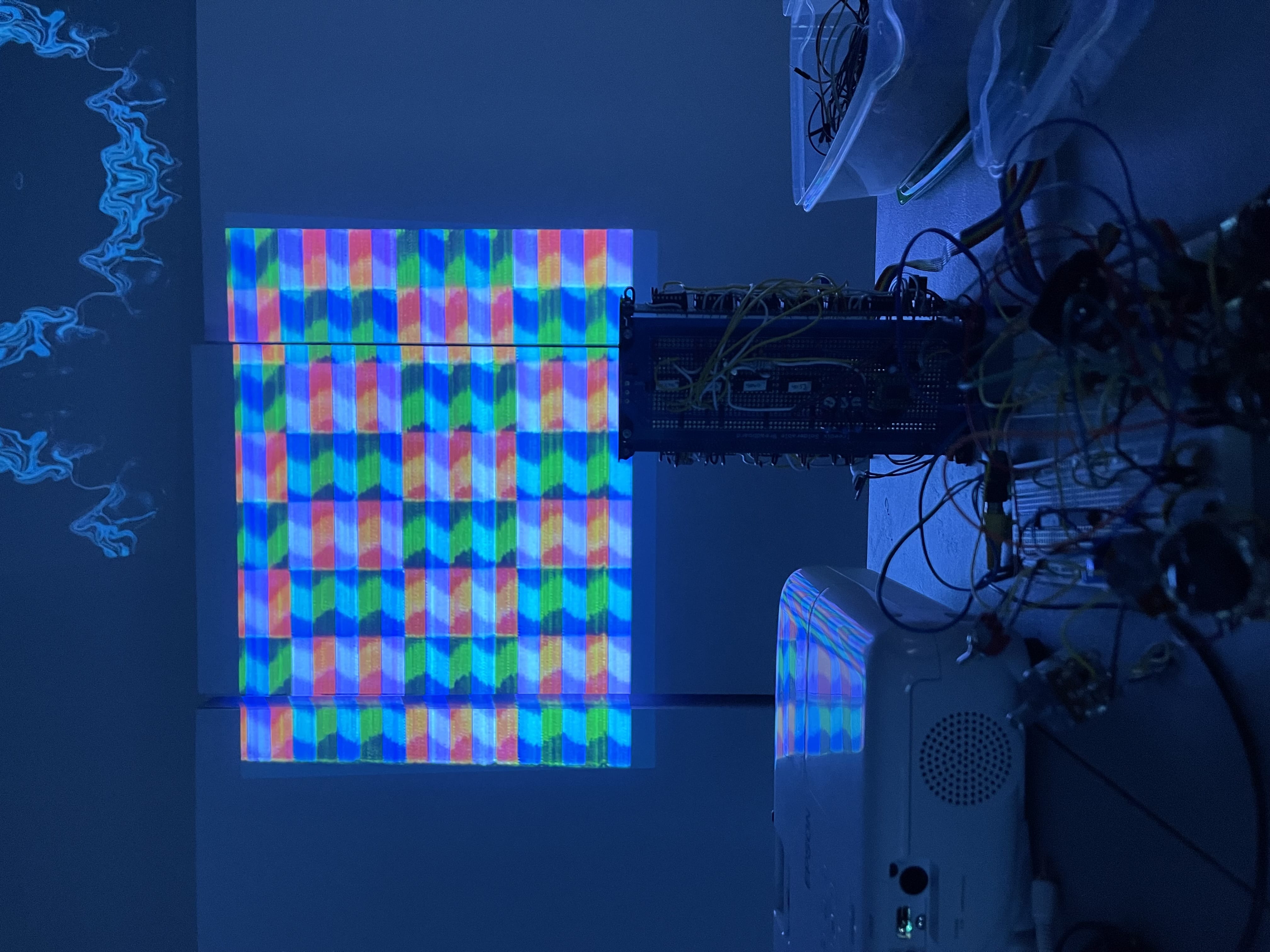
This version of the circuit generates multiple patterns and sends them to the red, green, and blue channels separately.
When the patterns overlap, you get fun mixed colors like cyan, yellow, magenta, and white!
Composing a circuit
This is what it looks like to operate this circuit behind the scenes.
At this point, everything was still implemented on a breadboard, so designing patterns means actually repatching the circuit!
Mixing patterns
To make it easier to perform with, I soldered together a hacky three channel mixer
It's made of three stereo potentiometers. A "mono" potentiometer has two poles and a "wiper" — if you wanted to fade a single signal, you would connect it to one "side" of the pot, and ground/0 volts to the other. The wiper is the video output, and it fades from 100% signal to 0% signal.
Each stereo pot has two of those layers, and can attenuate two signals. For example, the red channel knob might have vertical bars and horizontal bars coming in. The trick here is to connect them to their respective layers in opposite directions, so that as one signal fades out the other fades in.
To make the signals blend nicely, they're mixed through diodes, so they don't bleed into other parts of the circuit.
This is really really fun to play with in person. Eventually I want to build a nice console inspired by a DJ mixer!
Compilation
Here's a 45-minute compilation of video synth patterns I recorded with a cheap composite video digitizer.
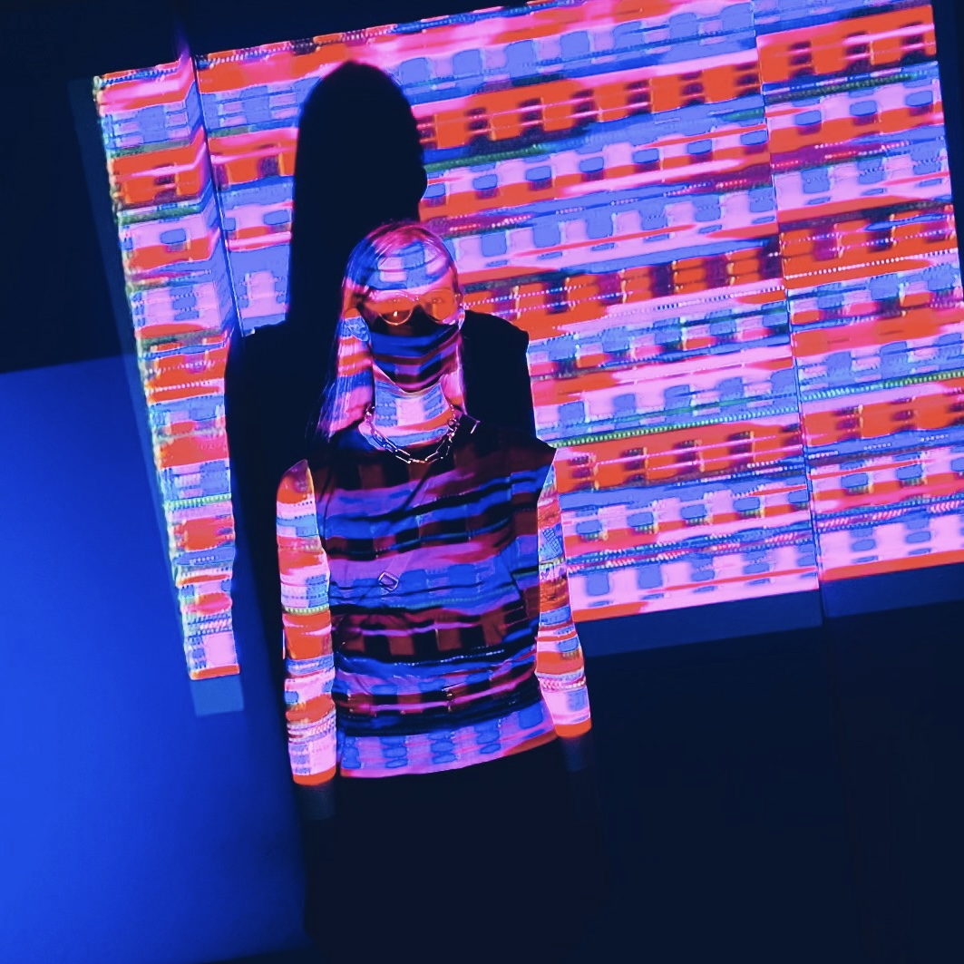
This was used as projected concert visuals a few times for my wife's band Maggie Gently! Here's a sampling of her latest album so you can try the full audiovisual experience:
Building the Sync Tower
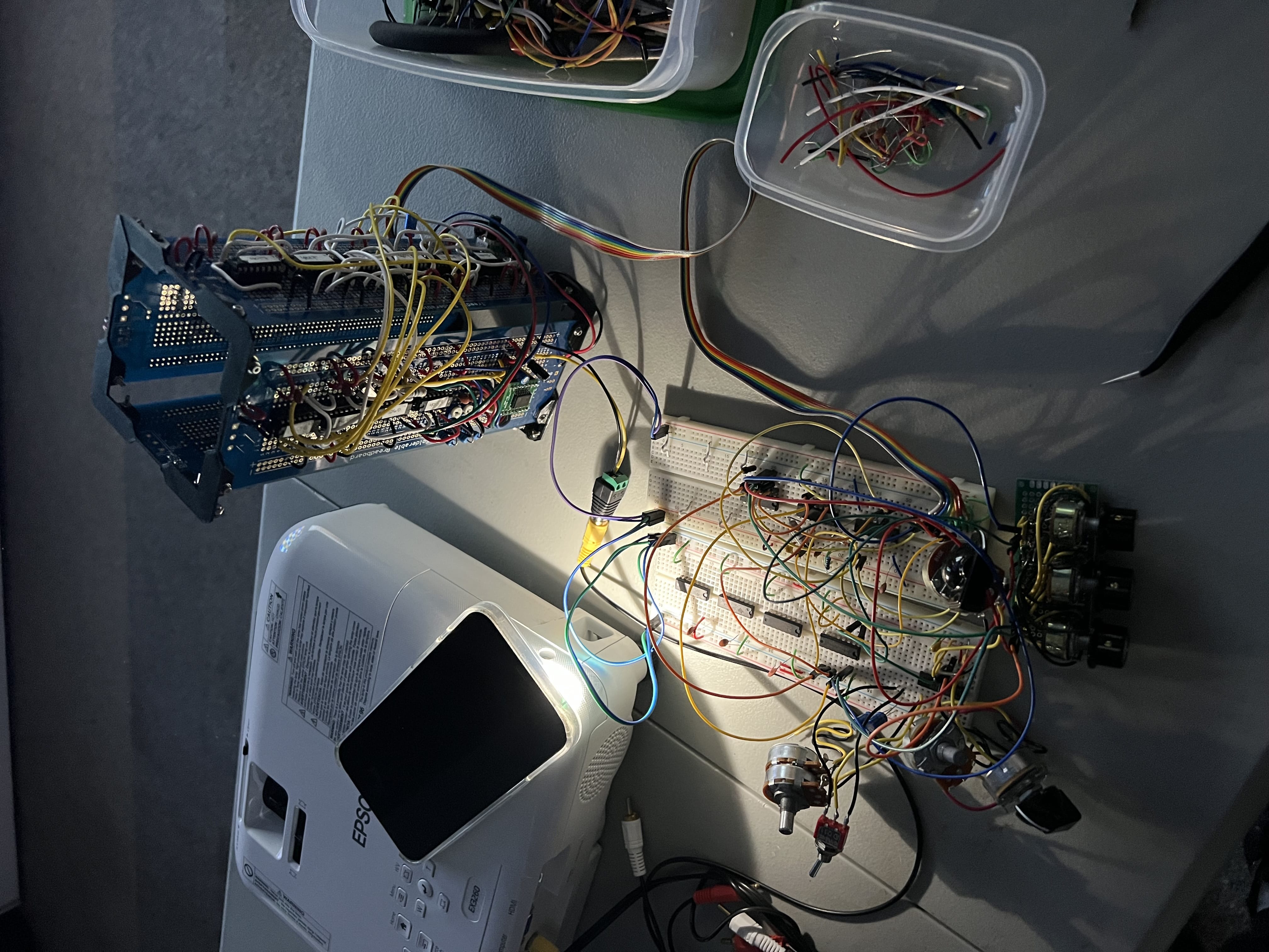
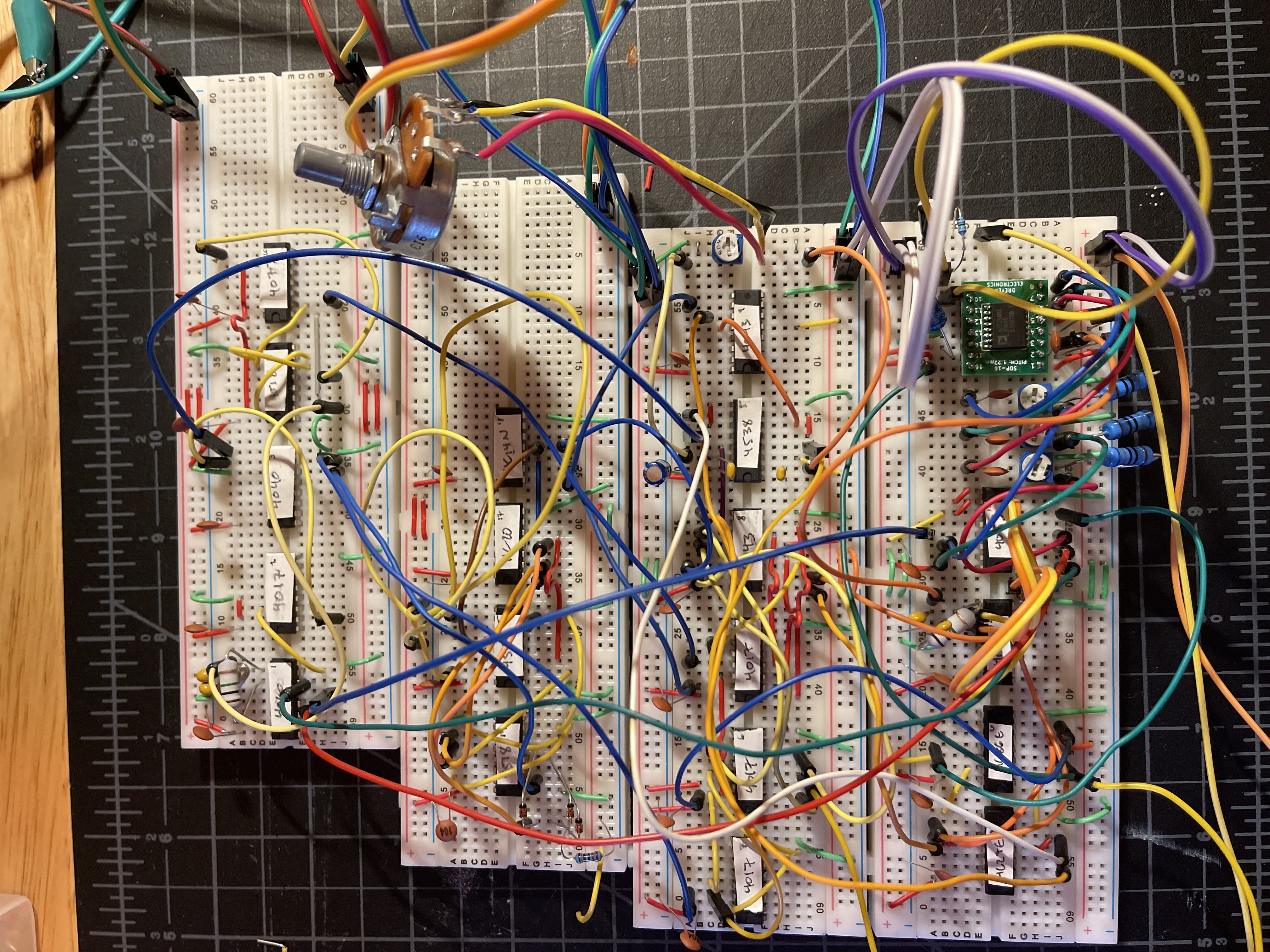
Here's what the sync circuit looks like on a breadboard. I took this photo (and like a hundred others) to document all the connections before I disassembled it and recreated it on perma-proto boards.
Installations
I brought this video synth to Gray Area for a "Bring Your Own Beamer" video art night. It was a hit! Most of the work there is digital art, so it was fun to bring an analog piece for a glitchy, wobbly, lofi vibe.
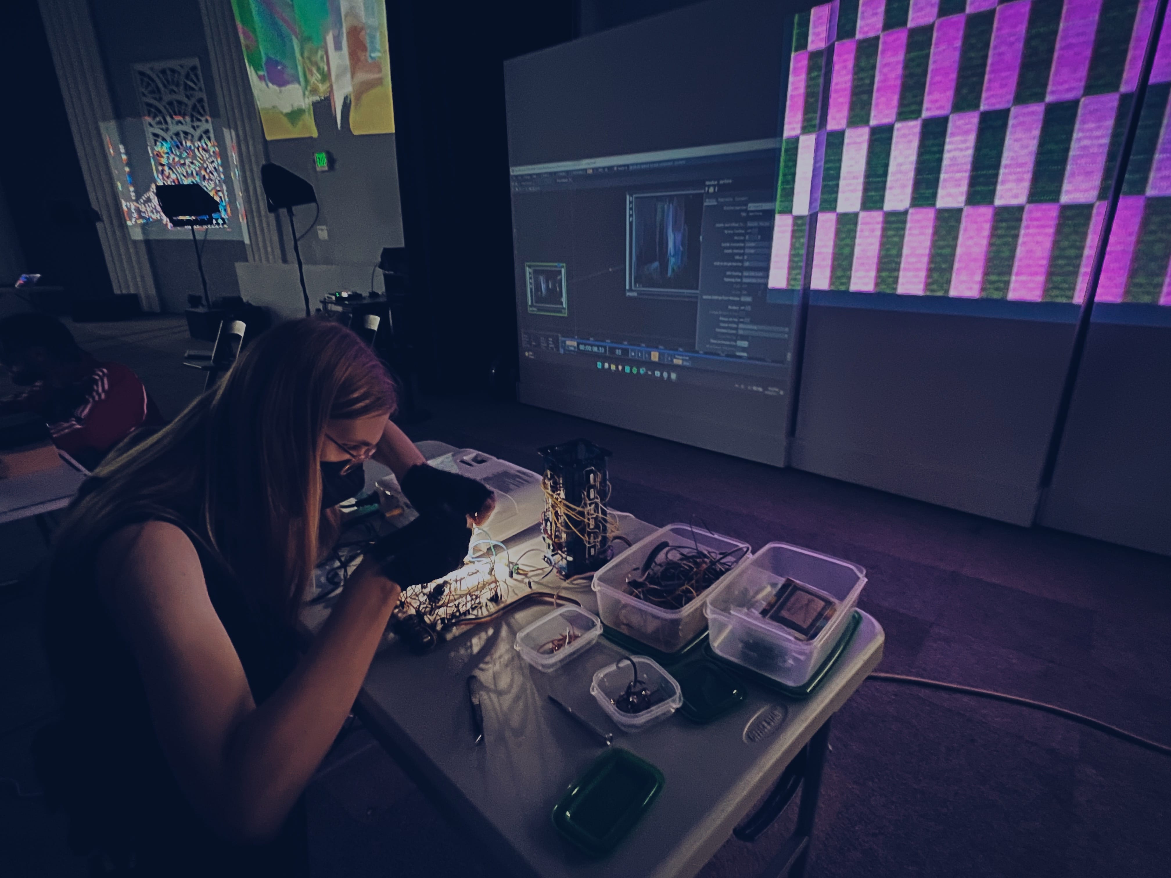
This is a pretty typical performing setup for the Sync Tower.
There's a rainbow ribbon cable going from the tower to the breadboards, which hold the pattern generation circuit. This contains some inputs to that circuit (frame start and row start signals), and some outputs back to the tower (RGB channels).
Preparing for a performance means setting up your breadboards with handy integrated circuits you want to use: binary counters, digital switches, logic operations (AND / OR / NOT / NAND / XOR), which I think is a fun way to approach designing visuals.
At the bottom you can also see that hacky little mixer I made!
The one downside of this is that it's hard for the audience to interact with and experience the joy of analog video. That led to my next project... the Video Cube.
