Pocket Operator Video
Spring 2025 • GitHub
The brief was pretty broad — they were asking for DIY ideas & designs that center pocket operators. They also listed some inspiring projects from the contest that accompanied the original launch, including custom cases, eurorack mods, alternative input devices, and more.
I immediately knew I wanted to submit something. Teenage Engineering has always been an inspiration of mine — I love their playful and lovingly crafted instruments, and I wanted to make something that felt like the RMNA homage to TE.
Brainstorming
I had a few initial ideas:
Sweatshirt Operator
Solder tiny wires onto all of the buttons of a Pocket Operator, then connect those to e-textile soft buttons on a comfy sweatshirt with a PO-inspired design on it. I've experimented with e-textiles before and it's a really fun way to interact with electronics.
PO-Video
I've built a lot of video synths at this point, and I would love to try reconceptualizing them into a miniature, intentionally-constrained format. I've worked with some cool transflective two-color 400x240 displays that might be the right size, so it could have a nice consistent look too!
Some kind of sync pulse generator
Since pocket operators can synchronize to a simple square wave timing signal, maybe I can build something to generate that... like a crank, or a wearable that measures your heartbeat, or a pedometer! I've done an experiment with heartbeat-powered BPM in the past and found the sensor to be very finicky, but I'd love to revisit this.
I loved the whimsy of the Sweatshirt Operator, but ultimately I decided to go with the PO-Video — mostly because I wanted it to be real so that I could play with it :)
High-level design
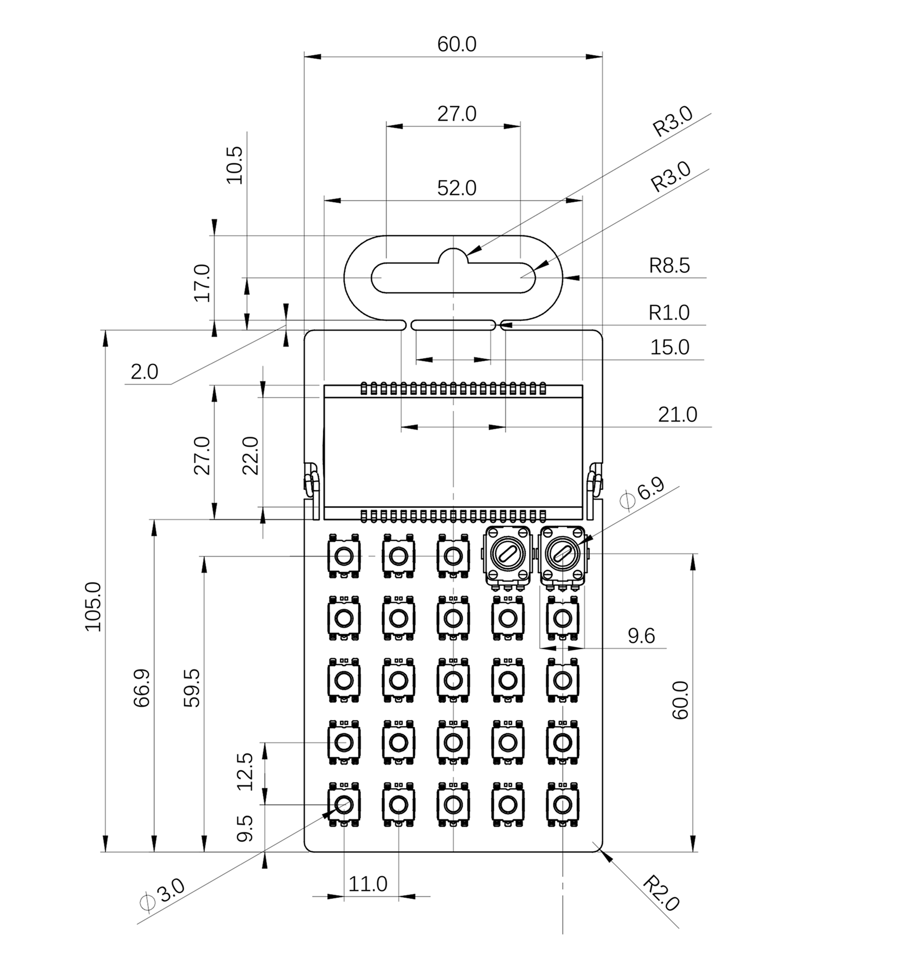
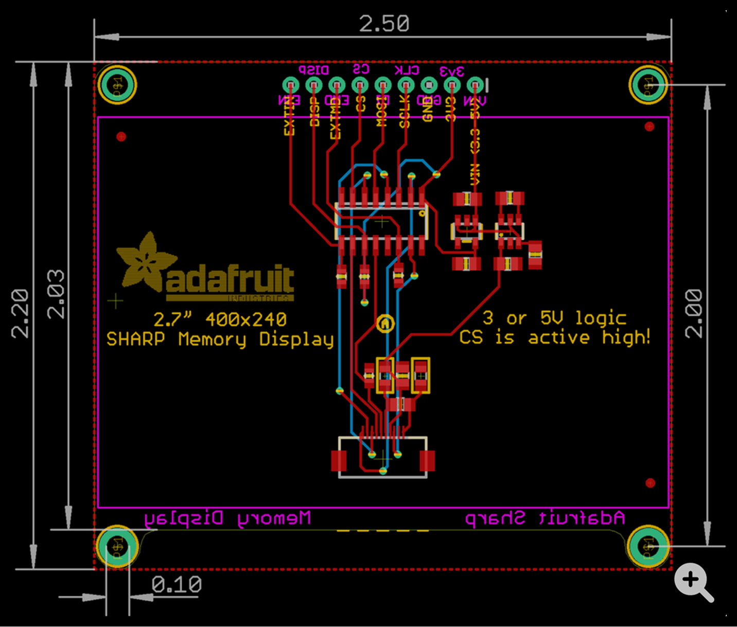
Next I had to figure out how to fit all the components into the Pocket Operator format. Fortunately TE provided files showing all the important dimensions of the pocket operator boards. I pulled up Adafruit's measurements for the Sharp Memory Display, and realized it's really close to the width of the PO circuit boards — it's just 3.5mm wider. I would have loved for it to fit exactly on the board, but figured that was close enough that this might work.
The next step was making a few mockups. I roughly scaled these images to be the right size relative to each other in Figma and started figuring out how I wanted to rearrange things. On the left is a photo of the PO-33 K.O.!, and on the right are three variations I considered:
- Extending the entire board vertically while keeping all the standard buttons and room for a model name + logo (which I would swap for an RMNA wordmark)
- Deleting two rows of buttons while keeping room for a model name + logo
- Deleting one row of buttons and the model name / logo
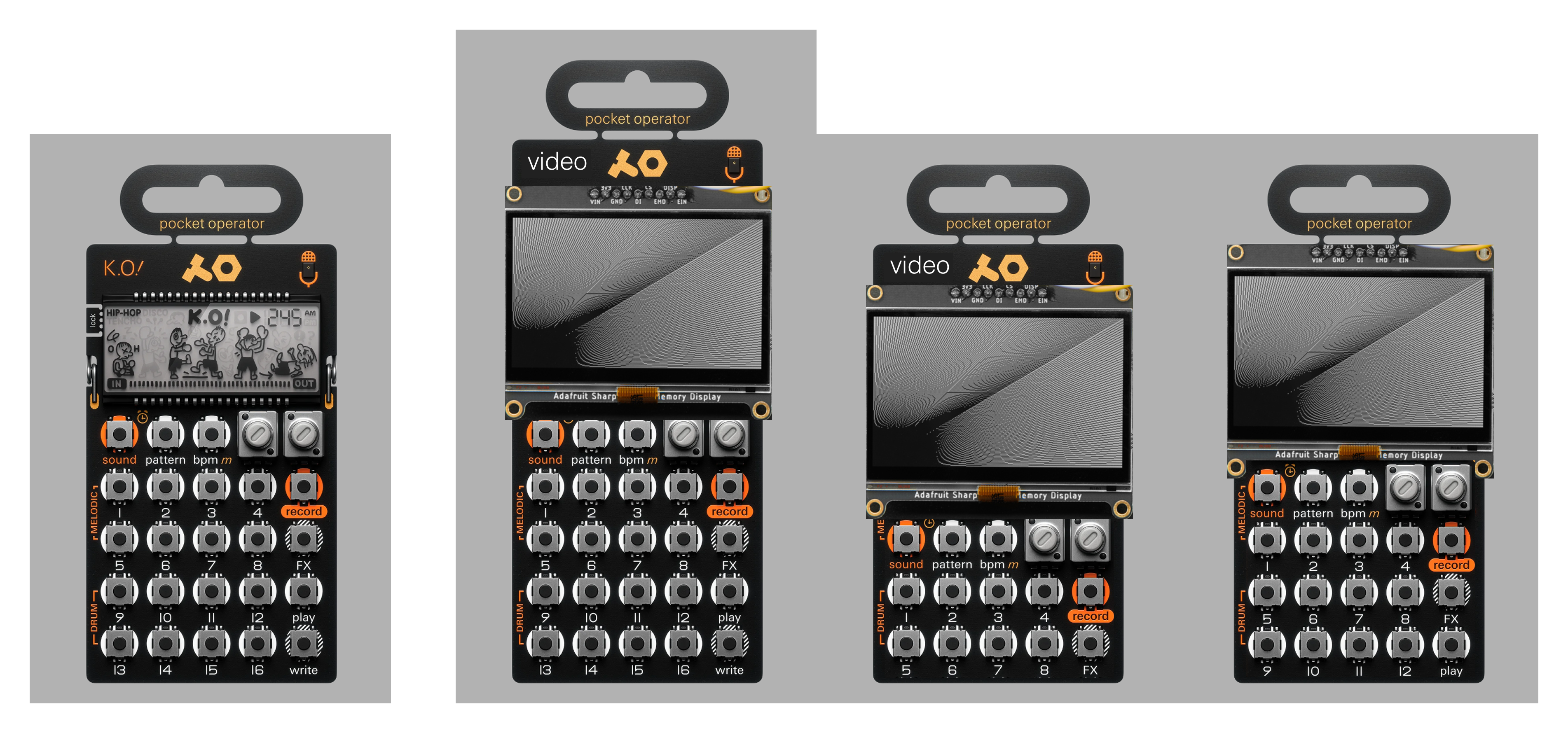
After looking at it for a while I decided option 3 was the best compromise — staying as close as possible to the original pocket operator form factor felt right, and I decided that the extra row of buttons would be more useful than room for branding (which I could display on a boot screen if I wanted).
Sacrificing one row of buttons would likely mean doing an 8-step sequence instead of 16, but that seemed ok too, since the visuals can move around a lot in just a single step anyway.
Inputs
After reflecting on the past video synthesizers I've built, and brainstorming and sketching a bit, I had a rough idea for how I wanted the interface to work. The basic concept was similar to the Video Sequencer, in that what you see on screen is composed of several overlapping layers, each of which is like a "drawing tool" based primarily on some basic shape (circles, lines, triangles, etc).
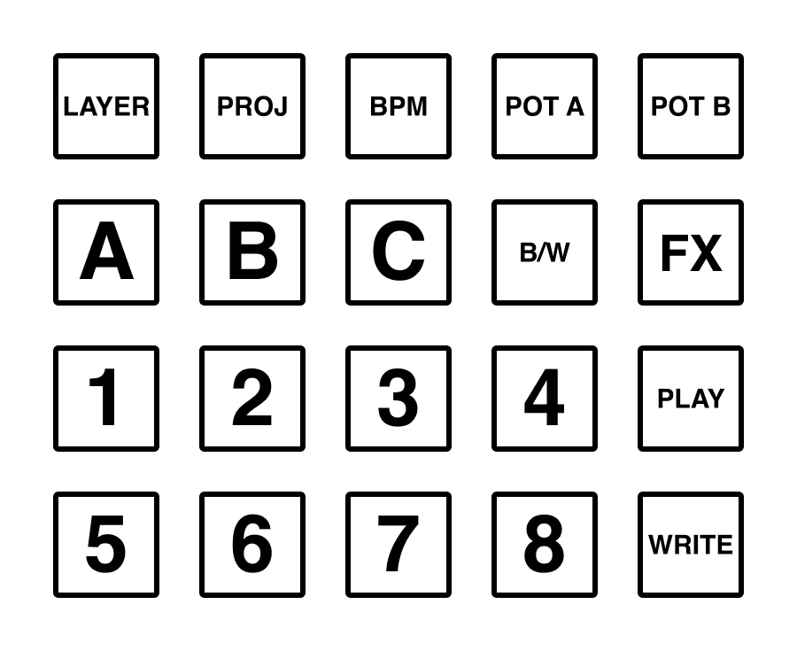
- The typical PO-standard buttons:
- Layer select
- Project select
- BPM select
- FX modifier for punch-in effects
- Play / pause
- Write mode
- 8 buttons to punch-in visual layers, or toggle steps on and off in write mode
- Three "style" buttons to select one of three options for how a layer gets generated — this would turn 8 drawing tools into 24
- A black / white toggle to set the primary color of the active layer
There were two major design questions I had related to the generated visuals:
- How can I make a two-color screen interesting to look at and draw on?
- How can I make the visual layers feel "deep" with only two knobs to control parameters?
At this point, it seemed like I had enough of the design pieces in place that I could start working on the circuits. I had a lot of other design work to do, but I wanted to do it with the actual working hardware as soon as possible. Both of these questions in particular required a lot of tinkering with working code, so we'll come back to these later.
There's only so much you can solve in your head!
Components & Circuits
Here's everything I used in this project:
- Adafruit Feather RP2040 with DVI (the GOAT)
- Adafruit 2.7" 400x240 Sharp Memory Display
- 2 Adafruit 10k ohm potentiometer with built-in knob
- 13 Adafruit NeoPixel Nano 2020 RGB LEDs
- Adafruit Maker Paste low-temp lead free solder paste
- Adafruit 400 mAh LIPO battery
- 18 SMD momentary tactile switches from Jameco
- 1 through-hole slide switch from Mouser
- 10k and 15k SMD resistors from Mouser
- SMD diodes from Mouser
- 2 3.5mm TRS jacks that I had lying around and forget where they came from -- sorry!
The total cost for these parts (not including the PCBs) was ~$100 to assemble one PO-Video, and I bought some backup parts just in case I bungled something. Most of that cost is the screen though, which comes in at a whopping $45. It's so unique though!
After poring over datasheets and tinkering and measuring I started making a circuit schematic in KiCAD.
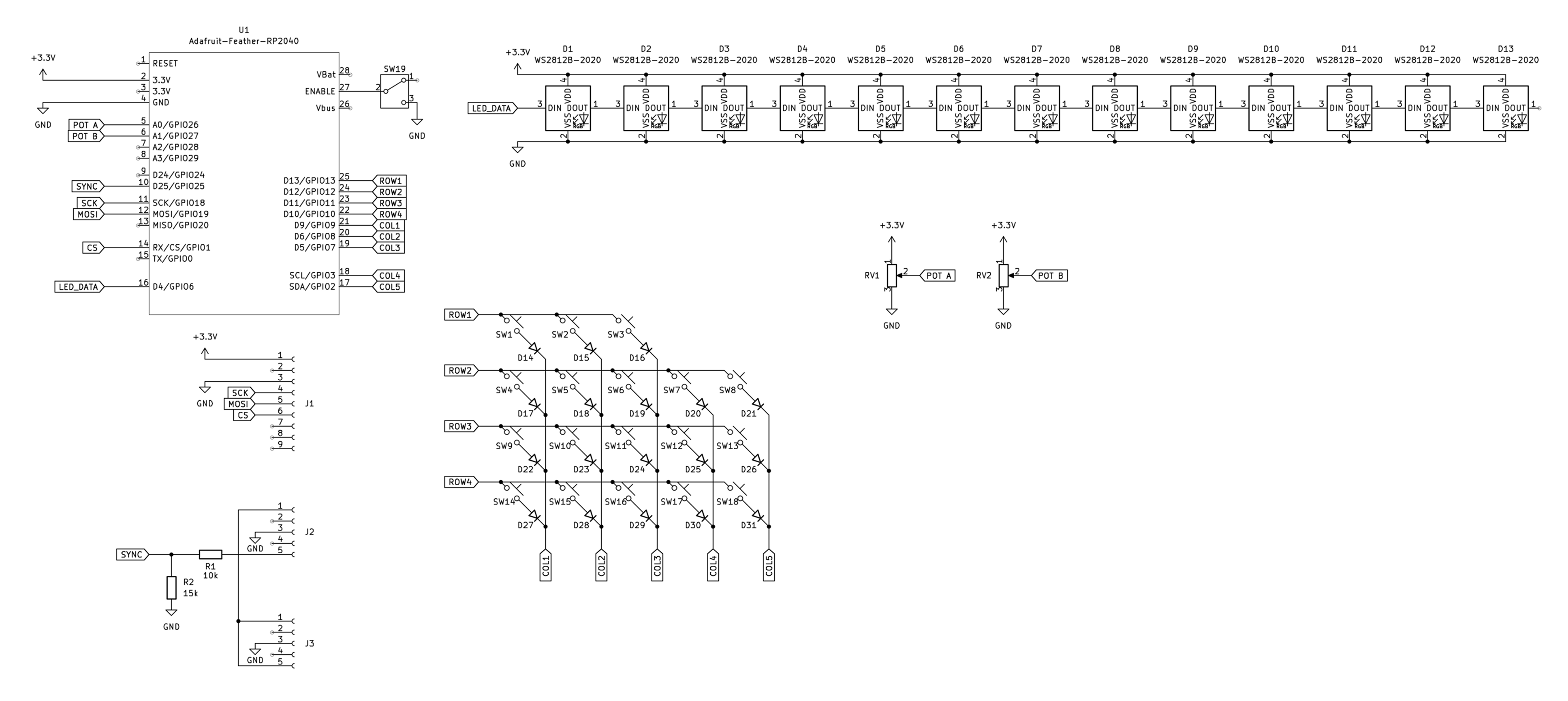
What's going on in here?
- In the upper right you can see a long chain of LEDs linked together
- Below that are the two potentiometers, connected to power, ground, and a pin on the Feather
- Below that and to the left is a matrix of switches and diodes to control the keyboard
- If you look up tutorials for how to scan a DIY mechanical keyboard you can see this same technique of using M columns and N rows to scan an MxN grid of keys. I used the Adafruit Keypad library and it was super easy!
- In the upper left is the Feather, with a switch that connects Enable to GND to shut it off, and a bunch of net labels to simplify the schematic.
- Below that is a header to connect the display
- Finally in the bottom left corner are the two audio jacks
- I won't get too into the details here, but Pocket Operators can synchronize with each other by passing audio and a sync signal over a TRS cable in a chain
- The PO video is designed to go at the end of that chain, and forwards mono audio to a stereo output, while sampling the sync signal!
I'll be honest I kinda YOLO'd this schematic and went right into PCB layout. I did test the memory display on a breadboard so I could get a sense of the refresh rate of the display, but I didn't mock up this circuit really. I tripled checked things and then tried to get the PCB done ASAP so I could send it off and hopefully have time to do a second revision if there was an error I couldn't solve with a few hacky jumper wires.
PCB Layout
I do not have a lot of experience doing this — I've made a few small boards, but this was definitely the most elaborate PCB I've made so far! The boards I made previously were simple enough that the layout was pretty straightforward. This one took some experimenting! Doing the schematic first is nice because KiCAD can tell you if you forgot to connect something in the schematic.
I realized that there was enough criss-crossing of traces that I would need a more systematic approach, and I settled on a basic strategy of doing vertical traces on the bottom layer and horizontal traces on the top layer. I'm not sure if there's a better standard approach but that seemed to work well enough!
This is a two-layer PCB, in that there are components on both sides, and little printed connections between them on both sides. Here are views of both layers combined, then just the top layer (red), and just the bottom layer (blue).
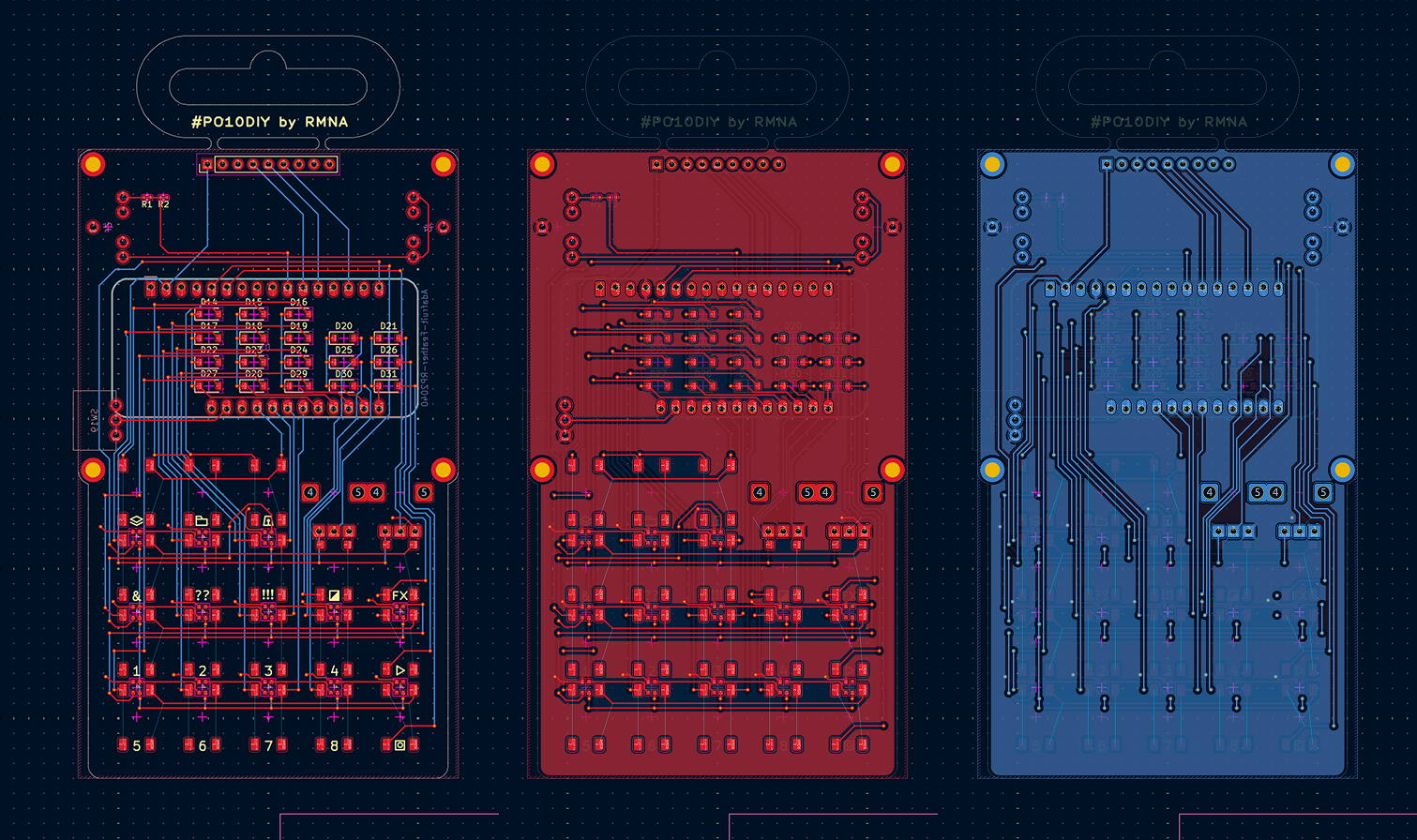
I made (at least) two mistakes...
- The power switch is connected backwards (you have to slide it down to power on)
- The schematic block for the Feather is for the generic feather, not the Feather with DVI — the top-right pin in this picture is connected to the LED data input, which would have worked... except for the fact that the DVI feather uses that pin for "Hot Plug Detect" (whether there's an HDMI cable plugged in there) instead of GPIO.
Fortunately neither of those are deal breakers! I was able to jump the LED data connection to the next pin over, and I'm just living with a backwards power switch.
I sent these boards off to JLCPCB, and it cost ~$50 for five boards, and to my surprise they arrived in ~4 days. Wild!
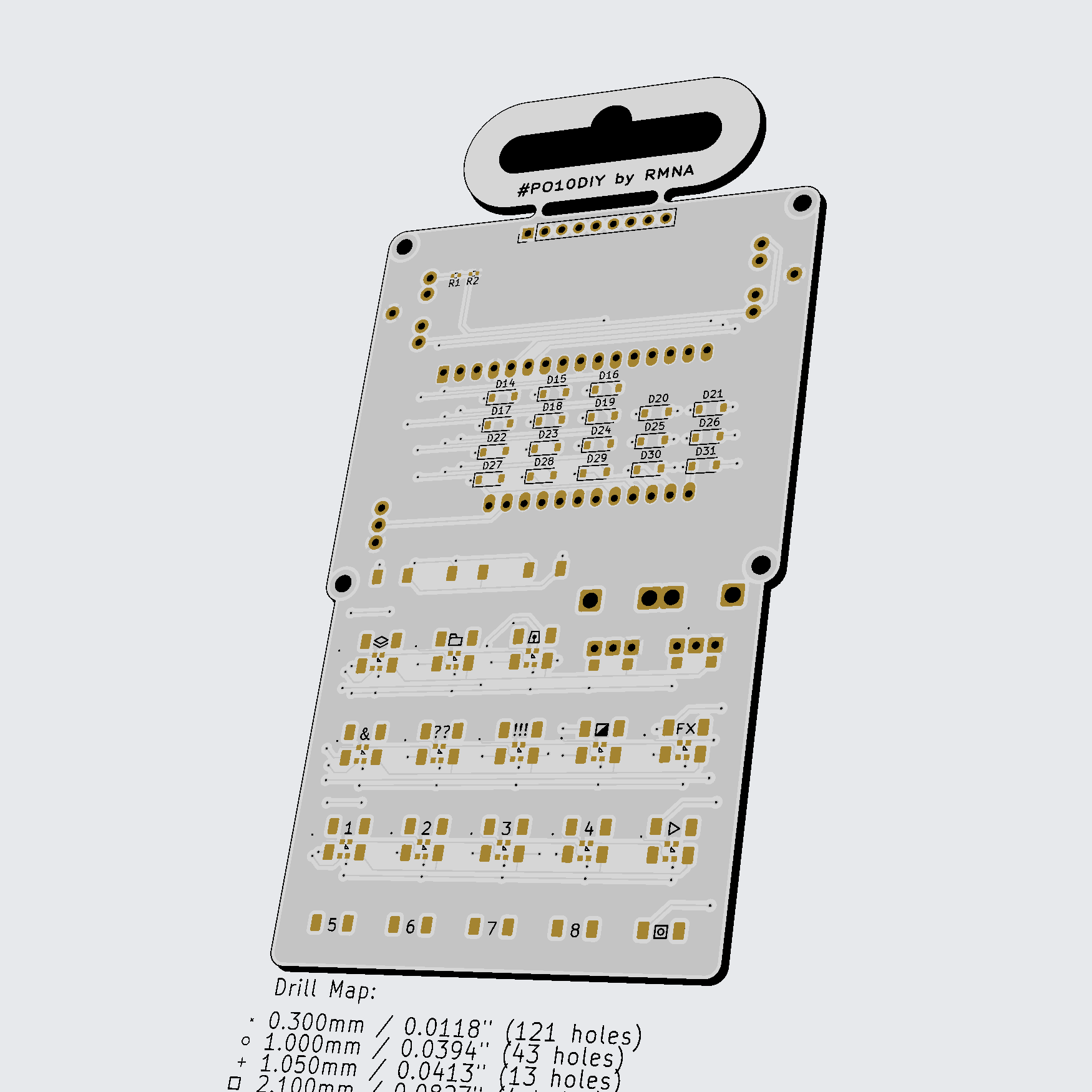

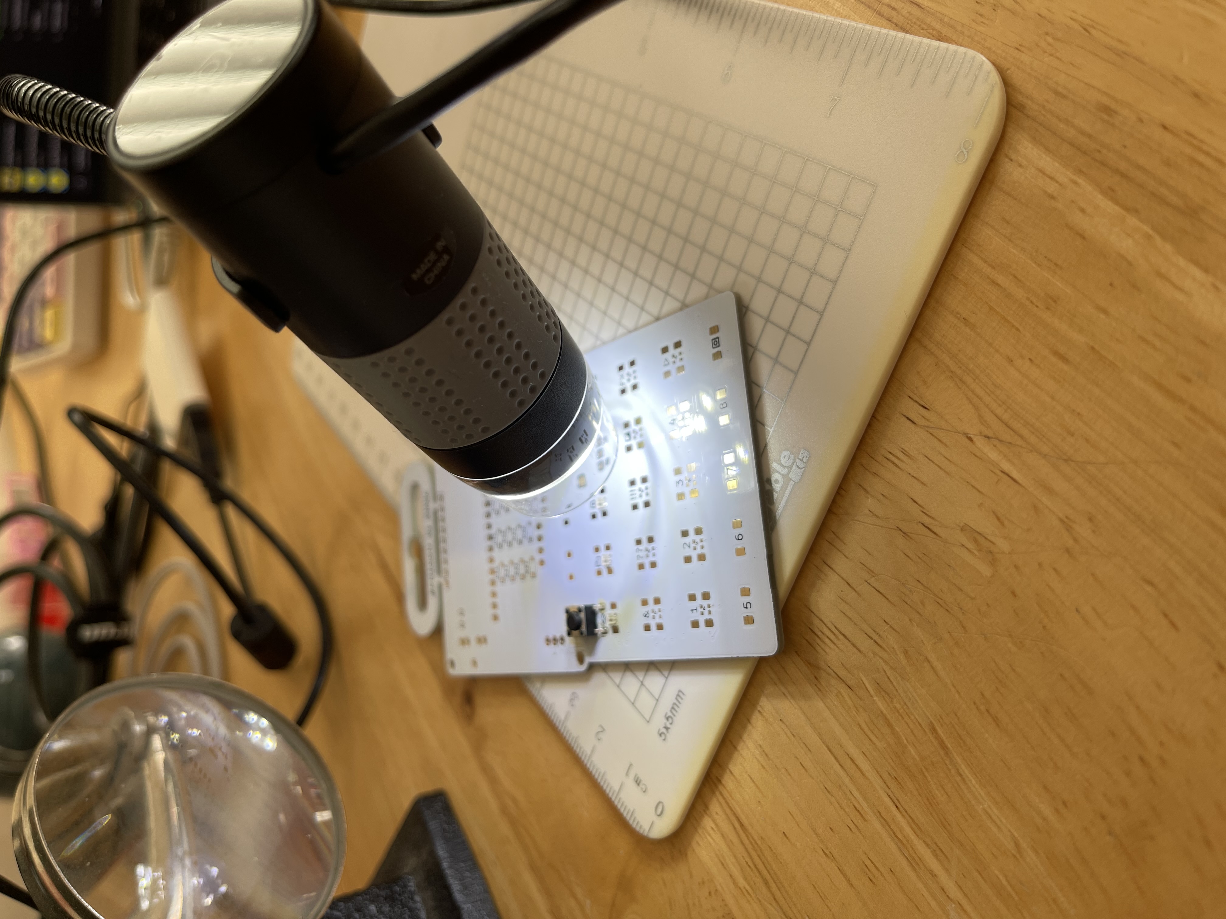
Assembly
This thing heats a circuit board from underneath, and you can attach small components with solder paste that turns from goo to nicely melted solder in just a few seconds. It's also good for loosening components that you want to remove or rework later.
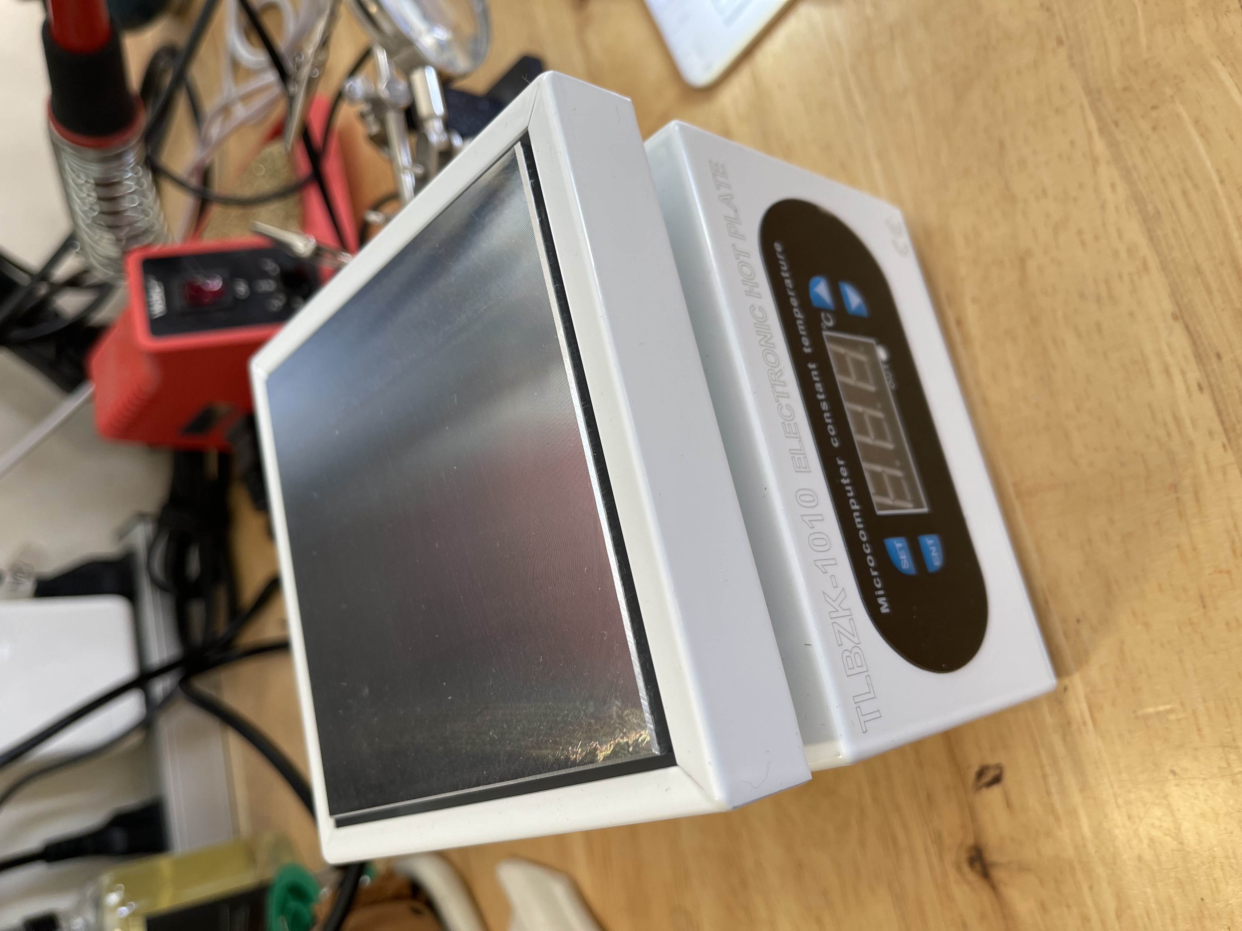
The paste is like little balls of solder suspended in some gooey medium. As it heats up the balls of solder melt and combine, and the white solder-mask keeps the solder stuck to the pads and not the rest of the board. The effect is that the parts kind of slide into place under surface tension.
In the meantime, I decided to move on and not have LEDs for the sake of time... I have a whole screen to indicate status with anyway :)
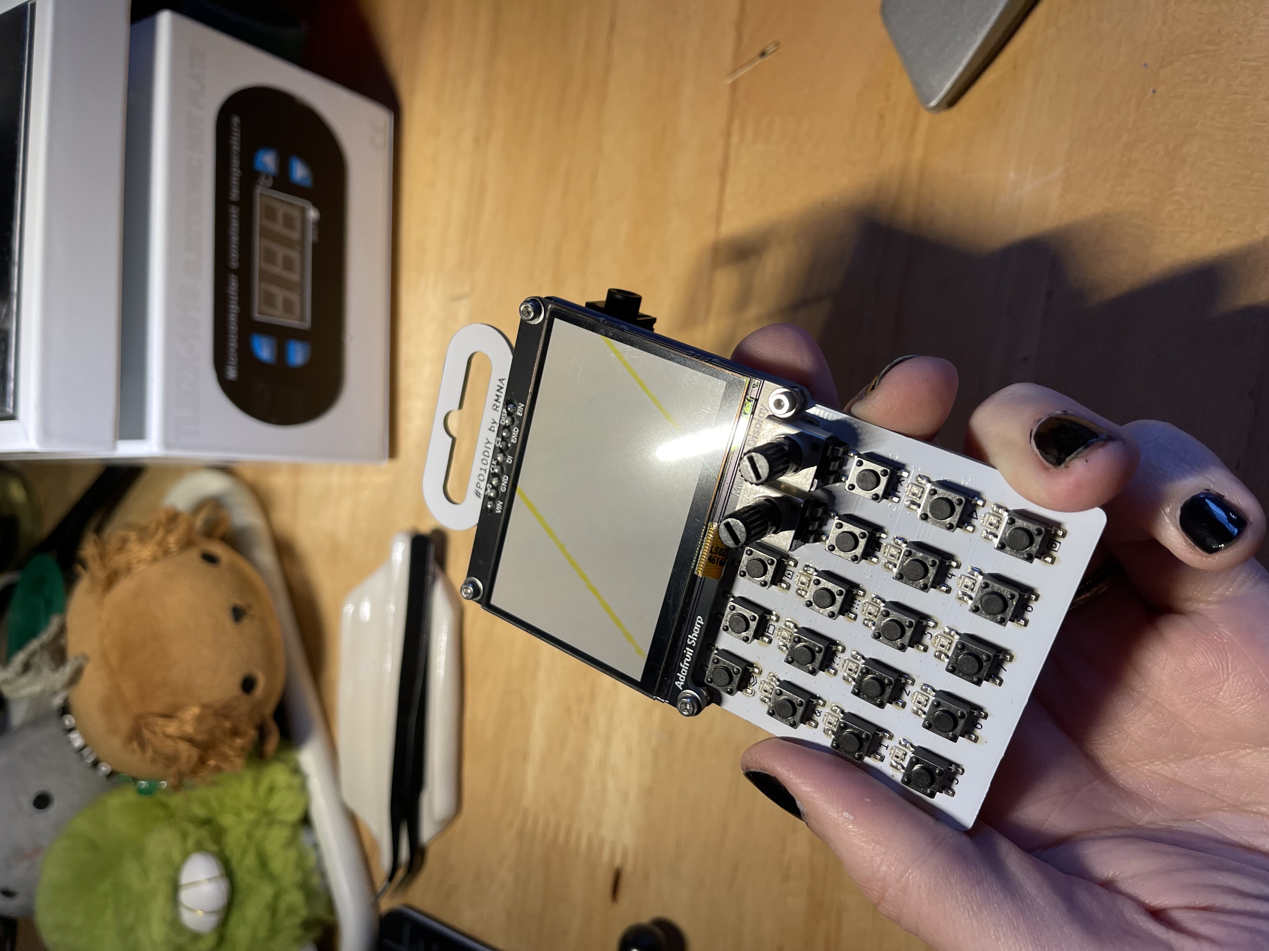
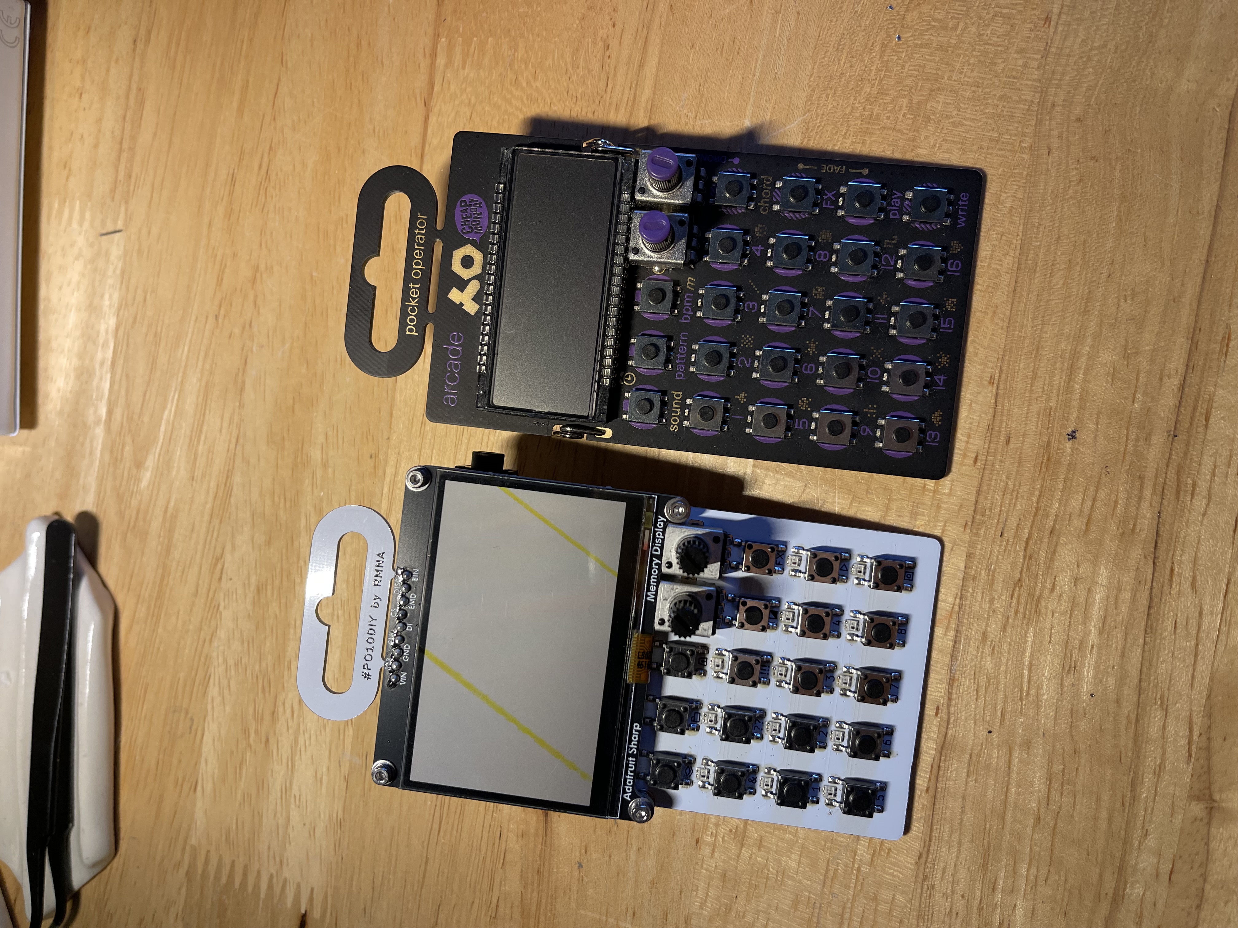
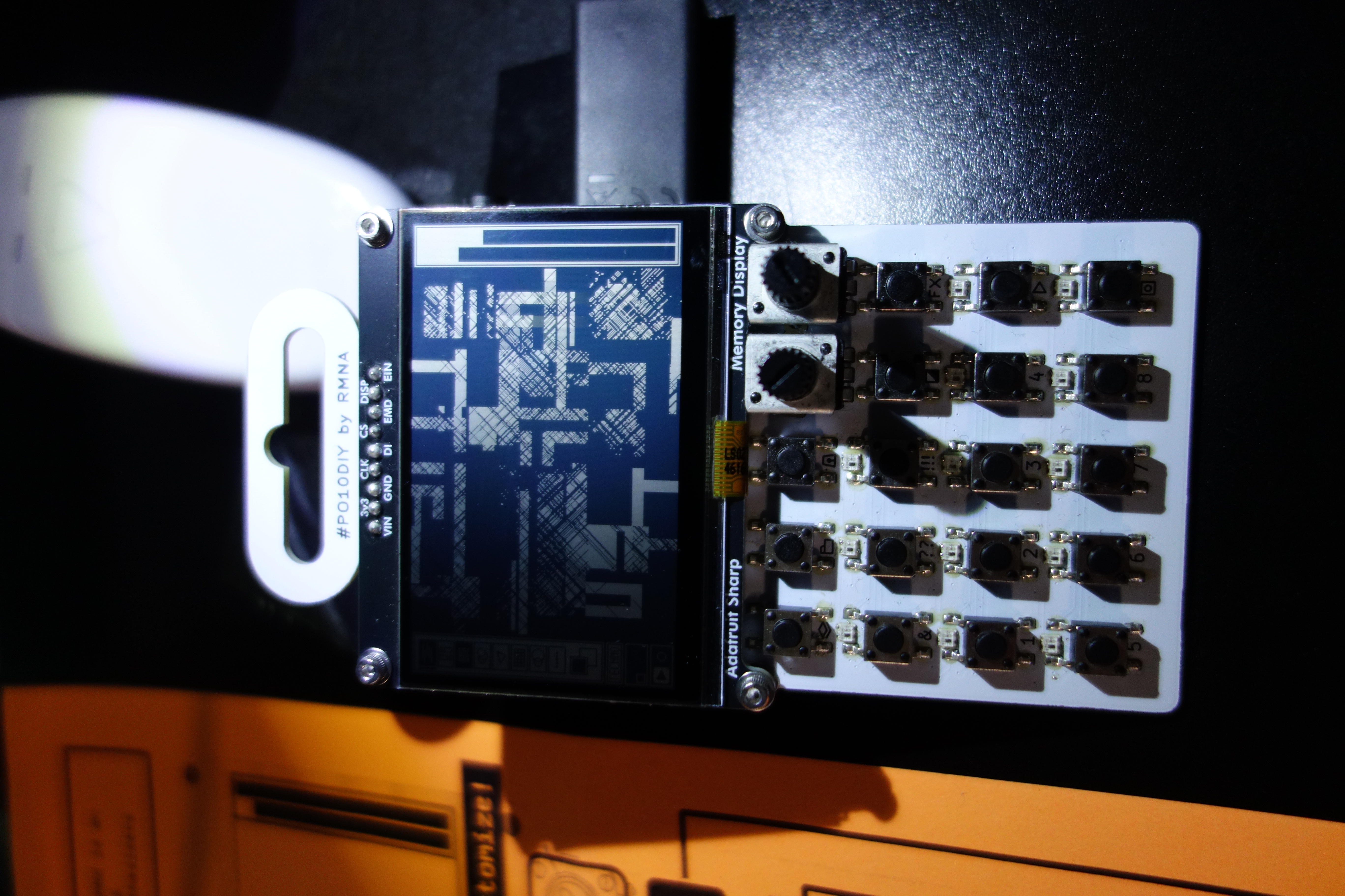
After a bit of hand soldering on the through-hole components, it was all assembled! Side-by-side with a real pocket operator, it's looking pretty good! Because I was using larger NeoPixels instead of the tiny red LEDs on the official ones, I didn't have as much space for fun graphics below the buttons — there are some tiny icons there though. When testing all the components, I discovered that only the first six LEDs in the chain work... I'm not 100% sure why, but my hunch is that there's a wonky solder paste blob somewhere. There's actually a separate problem that makes the LEDs difficult anyway, so I wasn't too stressed about that — I'll mention that issue later.
Code
At this point I was able to test all the different components of this device together. And everything pretty much worked as expected! (except the LEDs)
So now I could move on to making it generate pretty visuals. I have a lot of experience building video synths with the RP2040, so I already knew how to make the sequencer part work, and I had some good ideas for visual patterns I wanted to try, but I had a big technical question to figure out first:
- Can I output video on the on-board display and the DVI port at the same time?
Long story short: yes! With some constraints.
- The memory display is 400x240, and has a refresh rate of like 20 frames per second
- The DVI port can work in a bunch of resolutions
- The board can do 400x240 (if you overclock the chip) and I wanted to use that with the 1-bit mode and have both displays share a single frame buffer, but I found that the PicoDVI library only allows a 640x480 resolution for 1-bit color, not even the pixel-doubled 320x240 mode I had used in my previous 8-bit color video synths
- I looked into trying to add a 400x240 mode, or even a 320x240 mode for 1-bit color, but the PicoDVI library is a bit advanced for me, even with AI helpers
- Furthermore, I couldn't get either display to even use an externally-defined framebuffer, but that seems more doable with time
- Anyway, I wound up using my double-backup plan:
- The memory display has 40px strips on the left and right side for UI, and a 320x240 "canvas" in the middle for art
- The DVI display is running in 320x240 8-bit mode, where the only two colors in the palette are white and black
- Every drawing operation that isn't part of the UI is performed twice: once on the memory display and once on the DVI display
- This is the double backup because it's the least efficient, both memory wise (we're not even using the other 7 bits of color depth in the DVI framebuffer!), and CPU wise (duplicating the drawing operations is wasteful), but fortunately the RP2040 is fast enough and has sufficient RAM to make these ineffeciencies a non-issue
So here, it's really just drawing one circle during each frame, which looks much better! In the final version of this project, the UI strips on the sides are redrawn from scratch each time (to cover up anything from the canvas that bleeds over), but the central canvas just builds up a big mess from small incremental shapes.
Once I got that figured out, I was really cooking, and started experimenting with patterns and shapes, and I returned to those design questions I mentioned earlier:
- How can I make a two-color screen interesting to look at and draw on?
- How can I make the visual layers feel "deep" with only two knobs to control parameters?
Let's dig in to each of these!
Interesting two-color patterns
With some experimentation I found a couple of guiding principles that made for interesting 1-bit visuals:
- Drawing with both colors at the same time so there's always constrast
- For example, the circle worm thing draws a circle that has a white fill and black outline, or vice-versa
- Things that are visually "sparse" or use little "ink"
- Drawing shapes with gaps between them (like the nested boxes, or grids of dots) helps show detail and create depth
- Ordering the layers from "biggest" to "smallest"
- The layers have a fixed drawing order, so Layer 1 is drawn first, then Layer 2, etc. so making sure that the biggest / most dramatic shapes are closer to the "background" means that it's more likely that things will be visible
- Making sure there's variation in motion, shape, texture, filled vs outlined, etc
- The "opposed rectangles" are big, filled, slow, and staccato, while the "oscillating circles" are light, outlined, fast, and smooth — this makes for interesting visual contrast!
Not every layer follows every principle, but I tried to just keep these in mind when working on the pattern code. I'll also note that as of today I'd say the existing layer options are very much a WIP first pass!
Efficient knobs
TE does a great job of making sure that even though you only have two knobs on a pocket operator, you can get surprising range out of each individual sound. One easy trick is to use a single knob to control multiple parameters, like a macro — a single knob might control both pitch and some aspect of the timbre, or volume and the decay time.
With a video synthesizer, you often have even more parameters at your disposal:
- Color
- X/Y position
- Horizontal / vertical size
- Rotation
- Oscillation speed
- Oscillation magnitude
- ...and so on
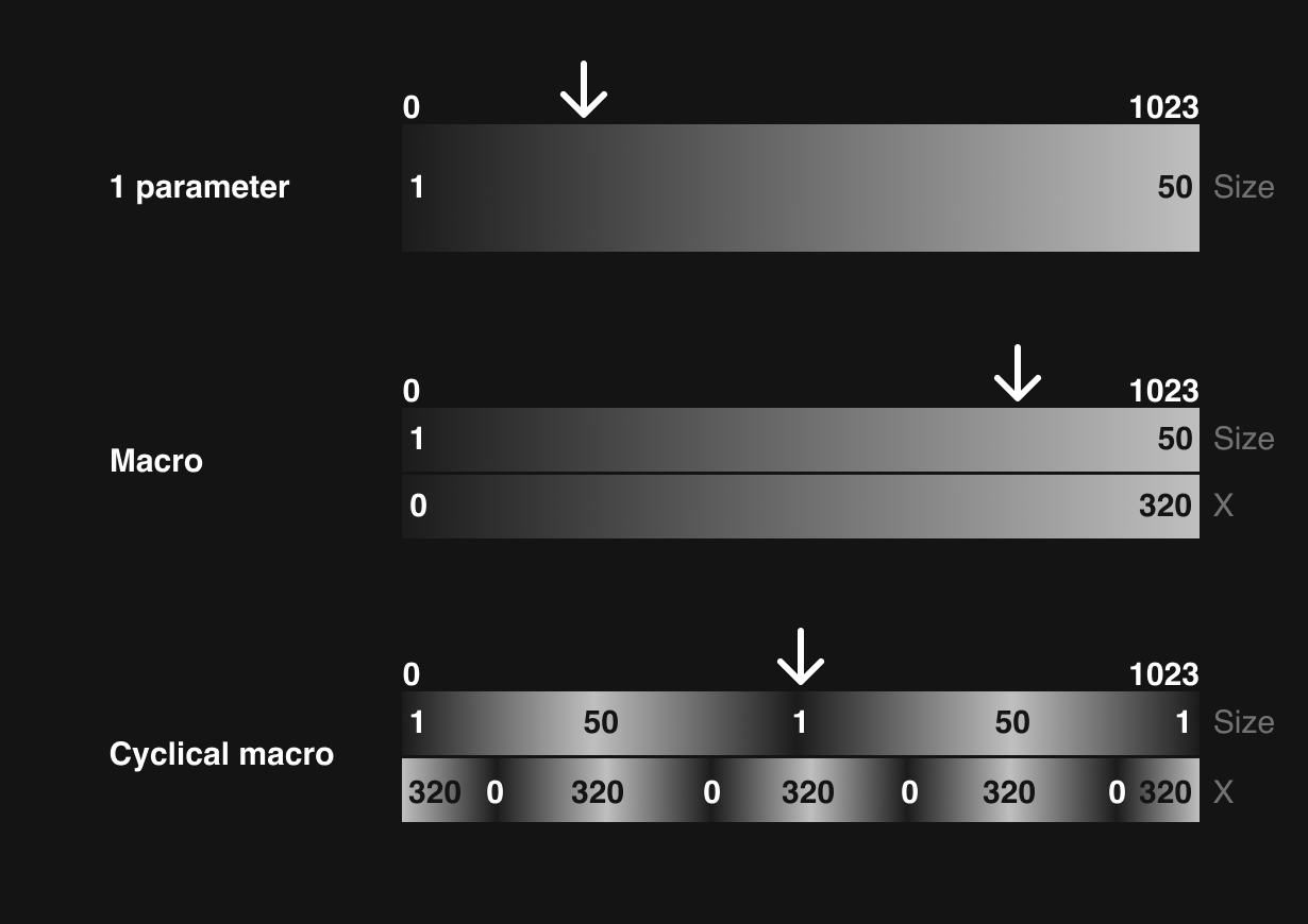
As an example, let's say we want to control the size and X position of a circle with one knob. In a typical linear macro we could say when the knob is at 0, size = 0 and x = 0, and when the knob is at 1023, size = 50 and x = 320. But what if I want a small size and a high x? There are some combinations that are impossible to achieve! A cyclical macro might sweep through the entire range of size values twice, and the entire range of x values five times, so that somewhere in the 0-1023 range, you can get almost every combination of size and x position, with smooth transitions between.
I defined a little function like this, and it works great!
long cyclicalMap(int pot, float multiple, float phase, int min, int max) {
  int range = max - min;
  float cycle = sin((pot / 1023.0) * multiple * TWOPI + (phase * TWOPI)) / 2.0 + 0.5; //0-1
  return(min + (range * cycle));
}
Interface
With those major technical and aesthetic design questions answered, the rest of the project was mostly just making fun patterns. The last major piece of work was the UI. Official Pocket Operators have very charming custom LCD screens that evoke tamagotchis or a game-and-watch, with little characters that animate back and forth to the beat and tell a little story. I wanted to make something cute, but not necessarily as abstract. I thought it would fun to have a generative art tool look kind of like an old drawing app like MacPaint — a computer art interface that required painstaking manual work twisted into something automatic and a bit opaque.
Below that is a BPM indicator ("TECHNO" / 140 BPM), a tiny 8-step sequencer (showing the active steps for the selected layer), and a play / write indicator. On the right side are two bars showing the values of the knobs.
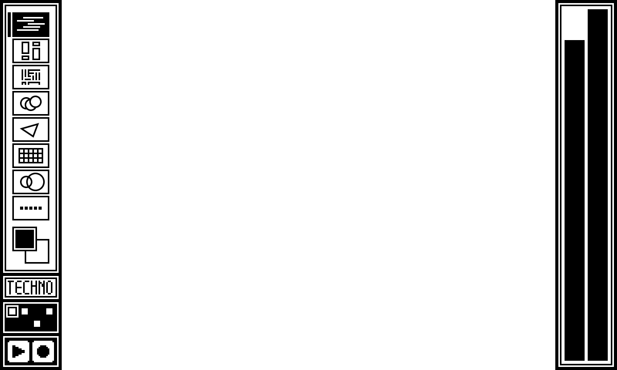
I designed that UI with vector illustrations in Figma, but I had to translate it to this 1-bit display. I could have drawn it with literal shapes, like the stuff on the canvas, but I thought that would be slow and tedious to program. So instead I exported pngs of all my UI elements and converted them into bitmaps using image2cpp. That tool will convert an image into 2-color b/w bitmaps, but then also format the data as char arrays that you can store in program memory on your microcontroller, so you don't have to load and decode image files.
For example, here's the char array version of the "Layer 1" icon:
// 'Layer 01', 24x16px
const unsigned char epd_bitmap_Layer_01 [] PROGMEM = {
	0xff, 0xff, 0xff, 0x80, 0x00, 0x01, 0x80, 0x00, 0x01, 0x81, 0xff, 0xf1, 0x80, 0x00, 0x01, 0x9f,
	0xfc, 0x01, 0x80, 0x00, 0x01, 0x80, 0x3f, 0xf9, 0x80, 0x00, 0x01, 0x81, 0xff, 0xc1, 0x80, 0x00,
	0x01, 0x9f, 0xff, 0x81, 0x80, 0x00, 0x01, 0x80, 0x00, 0x01, 0x80, 0x00, 0x01, 0xff, 0xff, 0xff
};
Pretty neat! This wound up being plenty fast, and has the added benefit of making it easy to invert the image too, which I used for the active states.
Gray Area installation
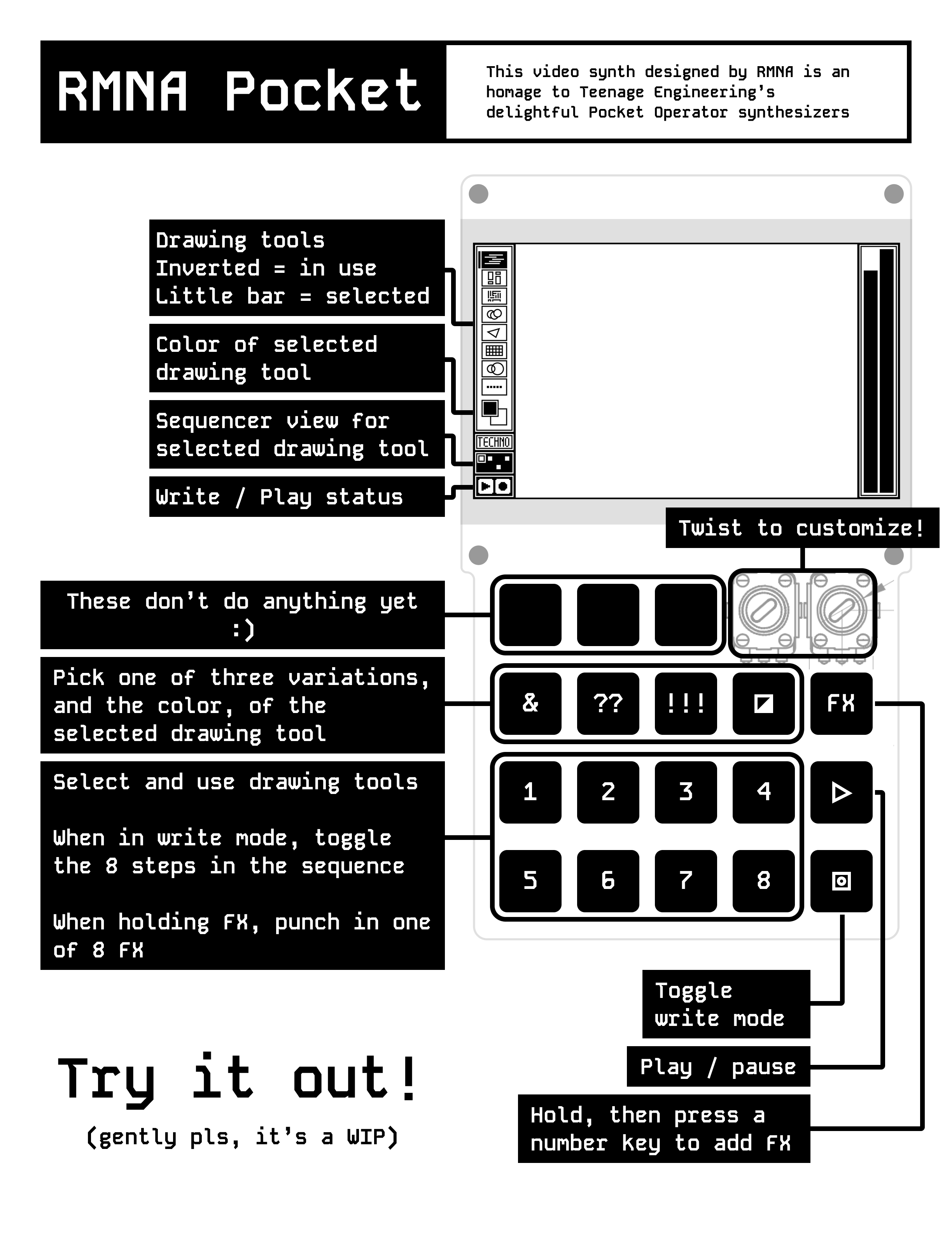
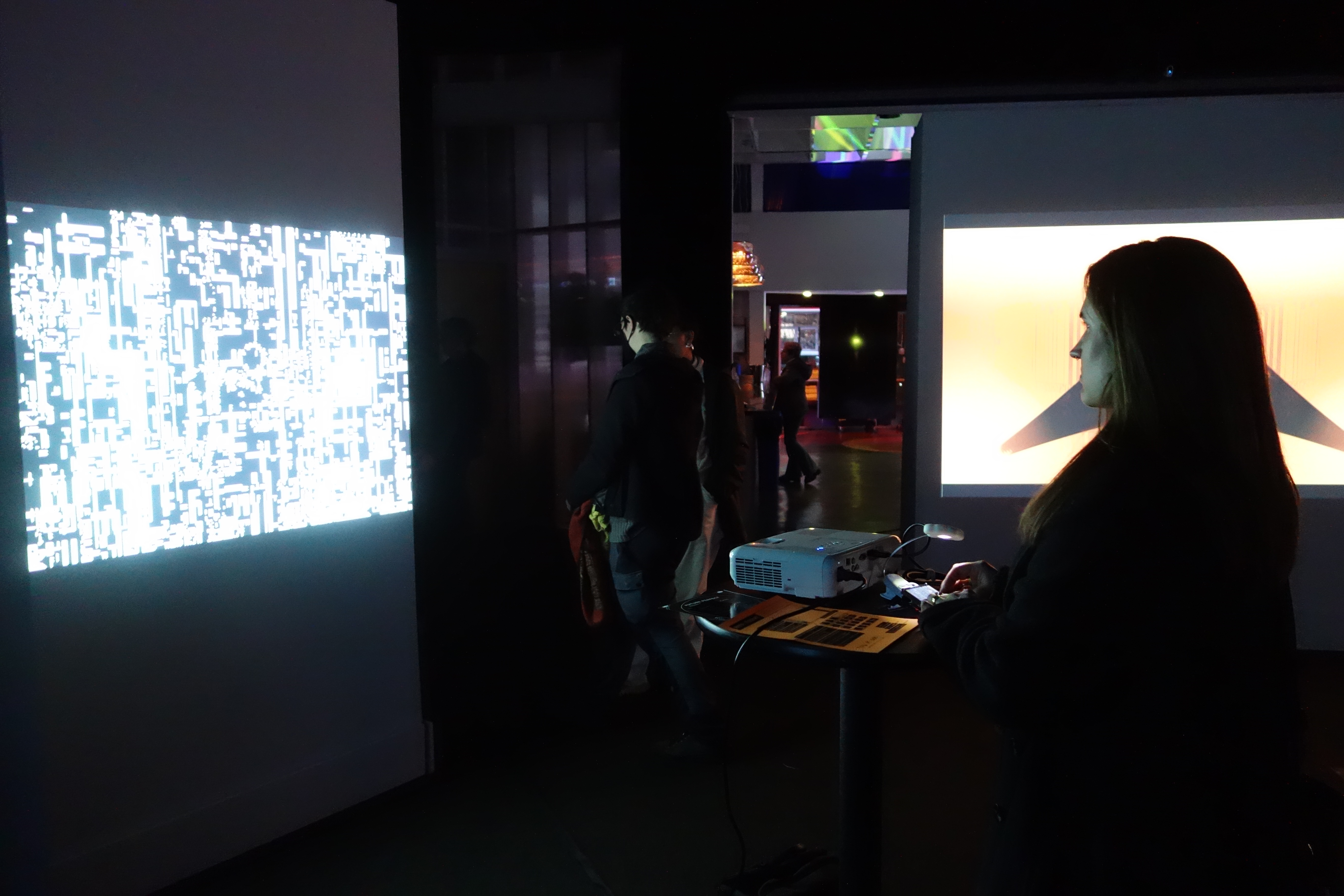
I recently showed this piece at Gray Area's wonderful BYOB video art pop up night. I always love seeing people engage with my work, and people seemed to really enjoy this one. This was also the first time I had really experienced the projected output of this thing, and I thought it really worked. The strict two color palette looks great in person — I think that was a very helpful constraint for this project. Anyway, here's the guide I printed out to leave on the table, and a few pics.
Future work
I have a lot of things I still want to do on this project!
- Add more layer variations, and make the generated visuals deeper and more interesting
- Refine the knob mappings (some of them are a bit jumpy or don't cover as many possibilities as I'd like)
- Make the PO-Sync signal actually control the sequencer
- Make the LEDs work (generating DVI video uses all of the Feather's PIO outputs, which are very convenient for controlling LEDs, but it seems like there might be a way to do bit-banged LED data or something)
Source code + project files
Once I clean up my code a bit and finish a few more things I may release the source code and project files (PCB layout etc) in case any of y'all want to take a shot at building one! So stay tuned :)