Video Cube
September 2022
During the show I did with the Analog Video Synth at Gray Area, I ran into my teacher Sean Hallowell from that Dogbotic workshop, who also was showing work there! It was the first time we'd met IRL, which was fun. If you think my projects are cool, just wait til you see his work.
He invited me to bring some of my work to another show at Syzygy for an event called Machining the Ghost, and I got to work designing a whole new interface for controlling my video circuits:
Design goals
I wanted the attendees of the show to be able to play, explore, and experience the magic of analog video synthesis. The interface had to be robust, inviting, and fun. Whether you play with it for 30 seconds or thirty minutes, it should be approachable and easy to experiment with.
Additionally, I wanted to stay true to the other Ramona Design Principles: I wanted to celebrate the fact that this device is hand-made, and show that video synthesis is something you can learn to do too — it's just wires and chips!
After letting it simmer for a while I decided that there were three main aspects of the video that I wanted people to be able to experiment with:
- Color — even without changing anything else, exploring different combinations of colors is fun and rewarding, and the colors in this circuit are really rich with texture and noise
- Patching — I wanted people to be able to easily cause big changes in what they were seeing, with some set of controls that's easier than manually routing and combining signals by connecting and disconnecting different chips on a breadboard
- Value — having easy ways to tune the frequencies of oscillators and smoothly move things around is fun and makes it feel like you have fine control over the pattern
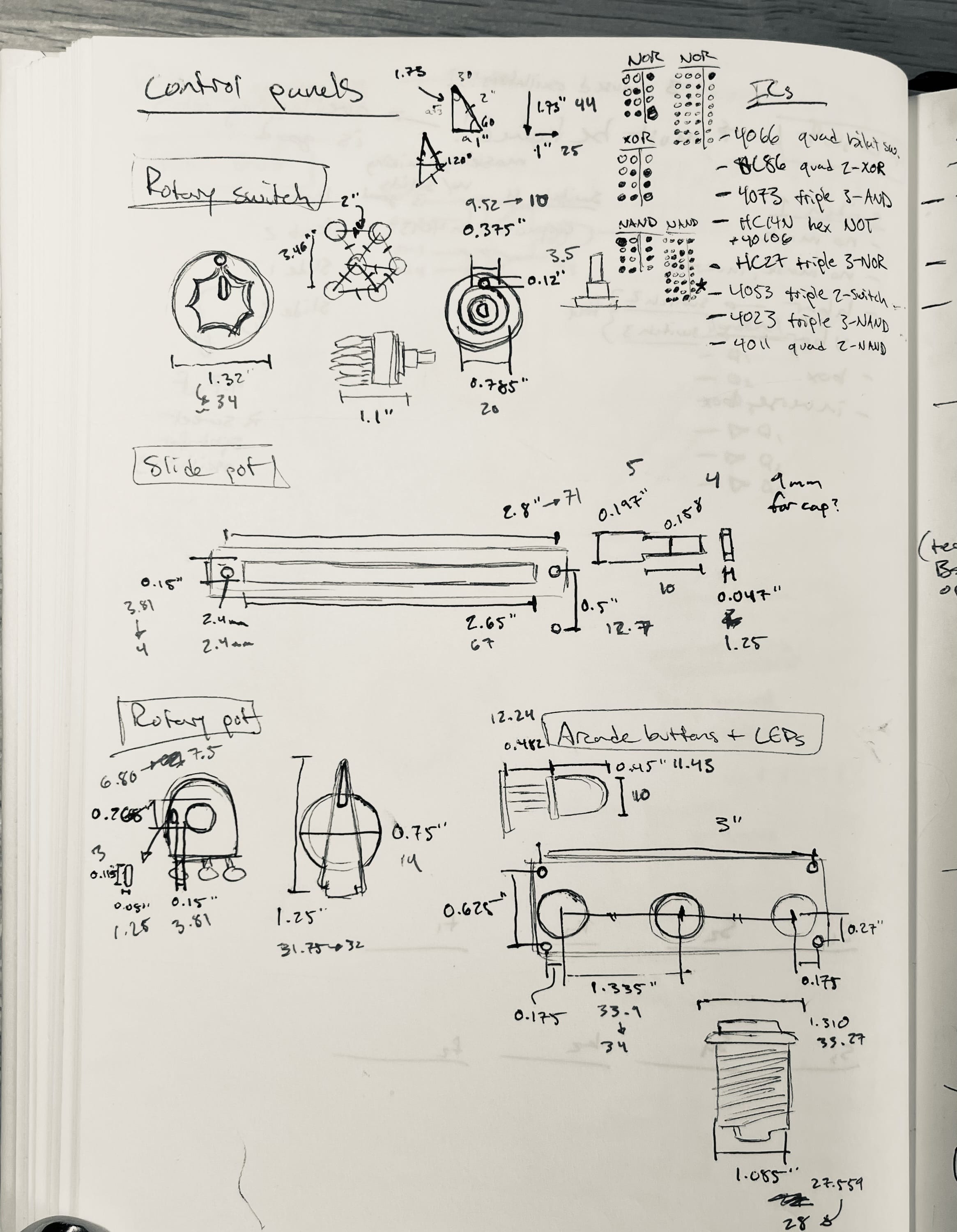
Value is the easiest one — I decided to use a combination of rotary potentiometers and slide potentiometers to make the important values of the circuit more easily tunable. These would controls things like the number and width of bars on screen.
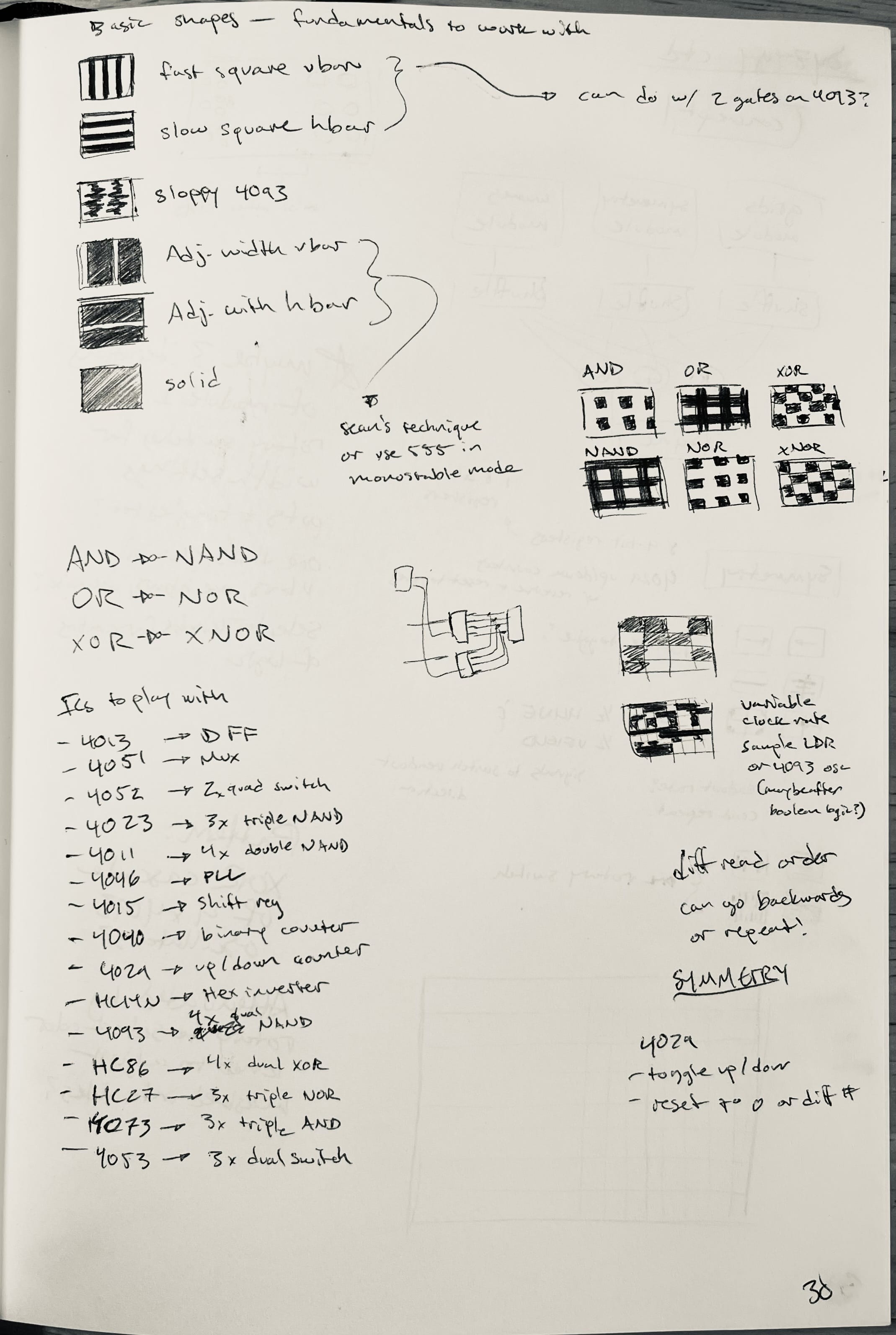
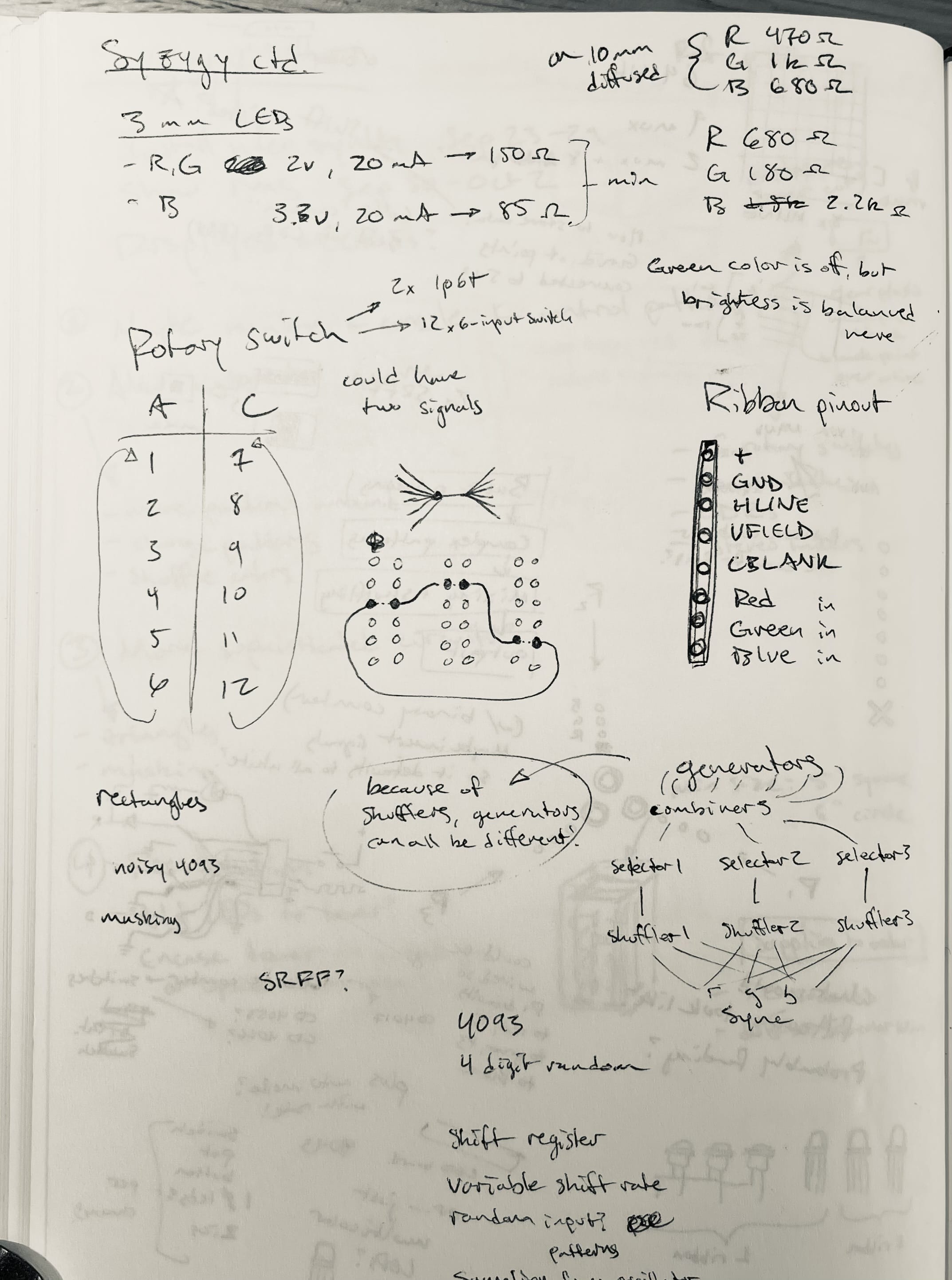
Patching is a little more complicated. After some exploration and testing, I thought it might be interesting to be able to quickly make and break connections between modules using rotary switches. I could build the circuit with a huge variety of oscillators and binary logic chips and allow users to easily click between different pairings of inputs and outputs by rotating a knob.
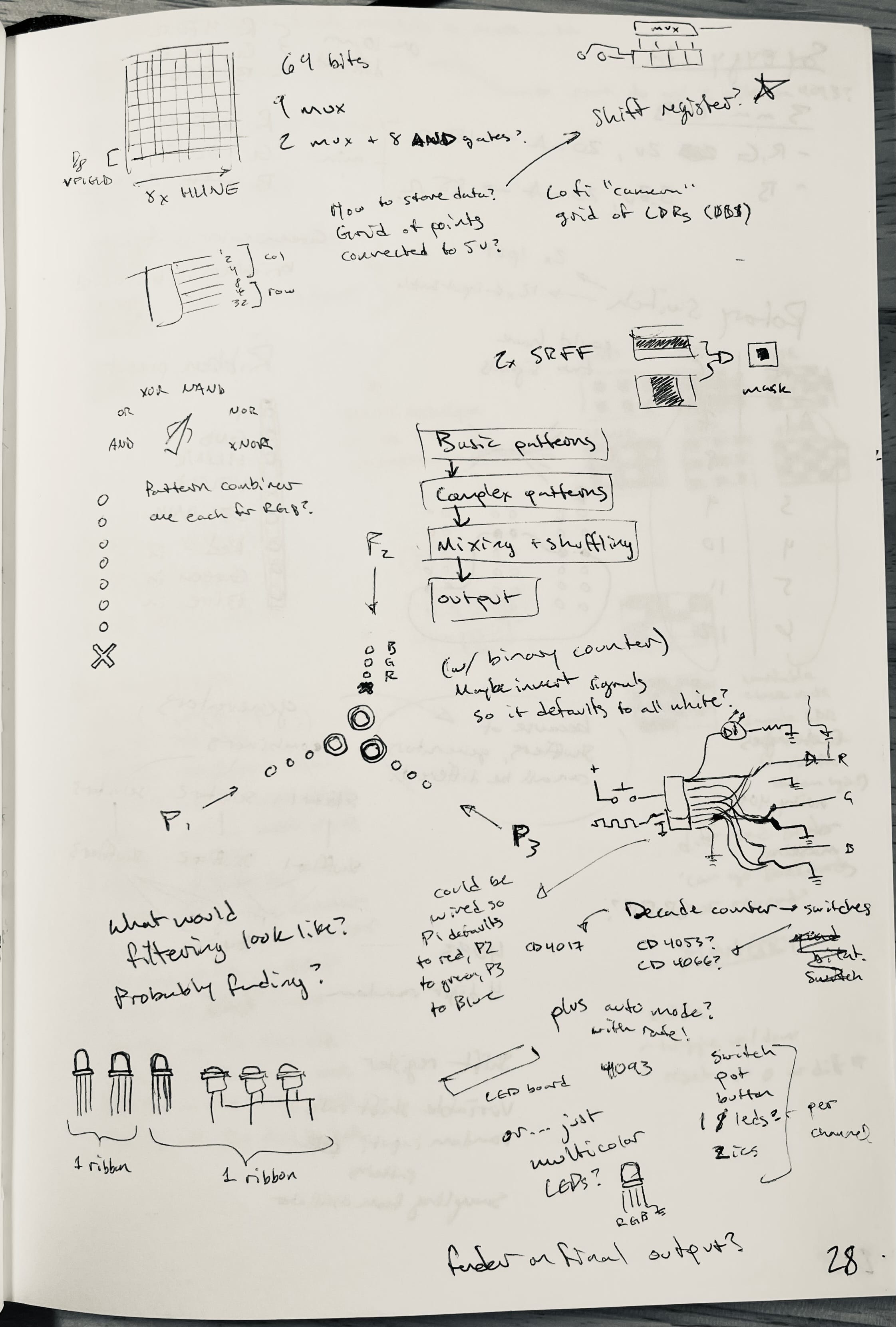
Color was the most fun control to design. I came up with a circuit I call the color shuffler — I had an idea to have a button drive a decade counter chip to control a bunch of digital switches that send a given pattern to the red / green / blue channels (and red+green, green+blue, blue+red, all three together, etc). And then I decided to build three of those! The synth would have three pattern layers (say, vertical bars, horiztonal bars, and squares) — and each of those could appear in red, yellow, green, blue, purple, or white (or not show up at all).
I hoped that having multiple layers of tunable patterns in different colors would allow a wide range of effects with a minimal number of controls. So, I got to work prototyping and testing…
Building the color shuffler
This was tricky, but I'm really proud of it!
Step 1
The color control was the first thing I wanted to figure out. In this video you can see the first baby steps of this circuit:
An oscillator is incrementing a 4017 decade counter about once per second. The 4017 has 10 output pins, and it just turns them on in turn, one at a time, as it receives pulses on the input pin.
I'm resetting it when it hits 8, and connecting the outputs to the LEDs you see here (and eventually, the digital switches in the final circuit.
The outputs of the 4017 are connected like this:
- Red
- Red and green (mixes to yellow)
- Green
- Green and blue (mixes to cyan)
- Blue
- Blue and red (mixes to purple)
- Red and green and blue (mixes to white)
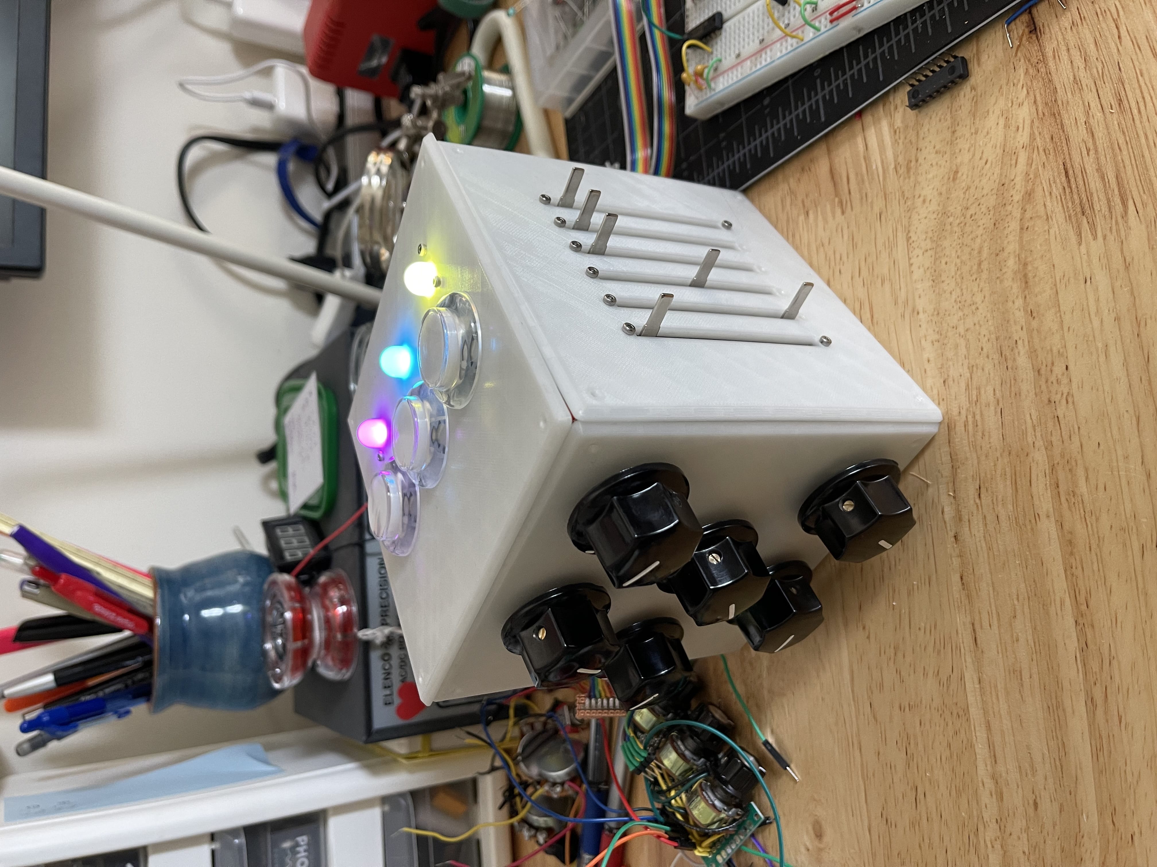
...and boom, you're scrolling through a rainbow! Instead of separate LEDs, I used a tri-color RGB led that has them combined in one package — these were the feedback lights you see on top of the cube that tell you what colors you've selected (reinforcing what you see onscreen).
Step 2
In this video, the shuffler prototype is controlling an actual pattern layer.
Part of what you see is always blue, but a separate layer is swapping through the rainbow sequence described above.
The decade counter isn't just controlling the indicator LEDs, it's also opening and closing digital switches that send this pattern layer to the red / green / and blue outputs of the video sync circuit.
The pattern has angled lines because it's projected at an angle on the wall I filmed this on :)
Step 3
This is the final component that got integrated as the top panel of the cube.
Now there are three color shufflers, each controlling a different pattern layer, and each controlled by a separate arcade button and indicator light.
These buttons feel really great to press: definitely hitting the marks of "robust", "inviting", and "fun"!
The rest of the circuits
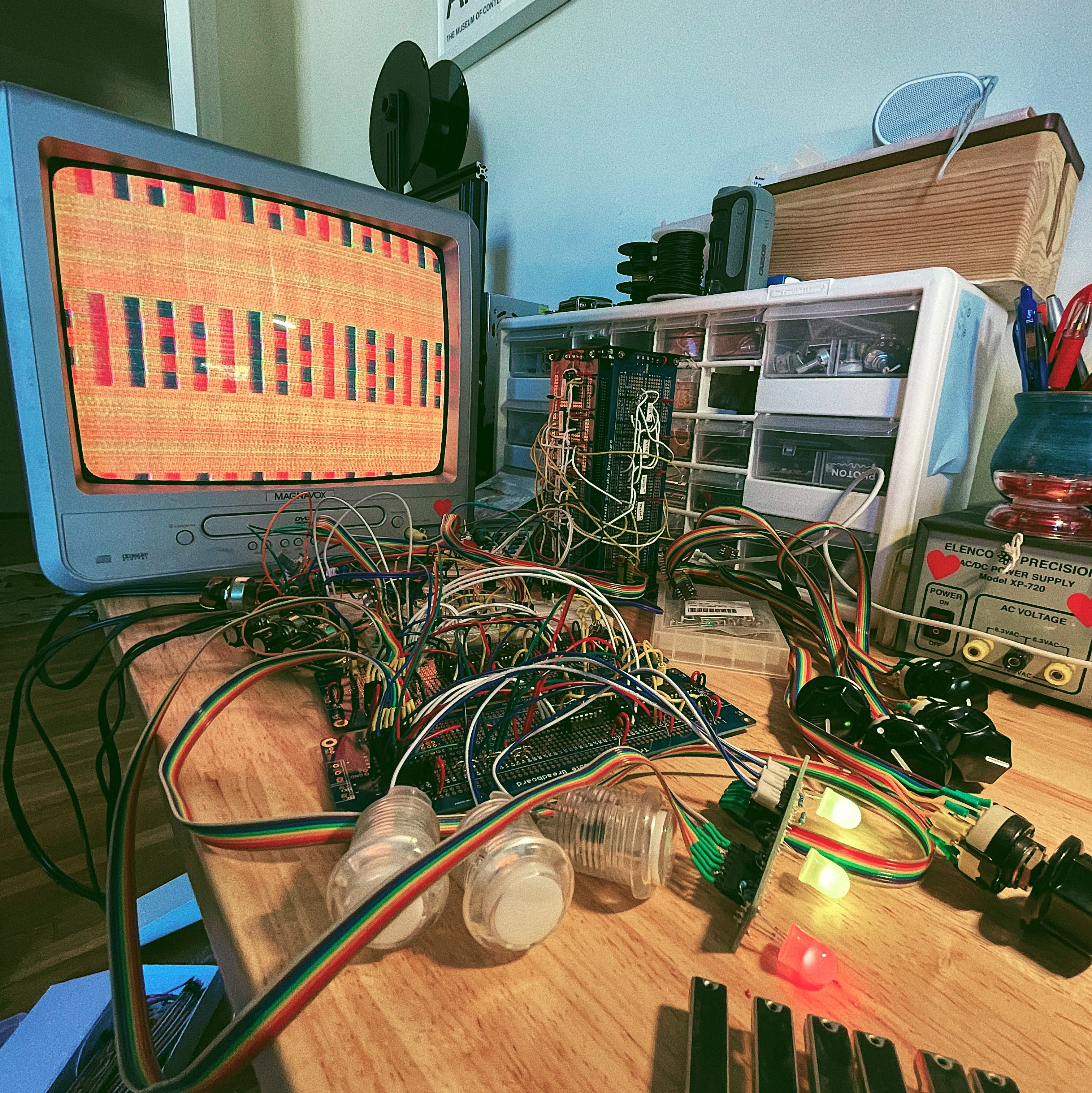
The pattern generation circuits were much easier to design and build, since I had a lot of experience putting them together quickly on breadboards for my first analog video synth. It was fun to explore different combinations of logic operations (AND, OR, NOT, NAND, XOR etc) and see what effect they had on the patterns.
At this point, the circuits were mostly functional, they just needed a suitable enclosure — one that was robust, inviting, and fun, while still honoring the handcrafted circuitry and showing my work.
...and that could be designed, printed, and assembled in the ~1 week I had left before the show.
Designing the enclosure
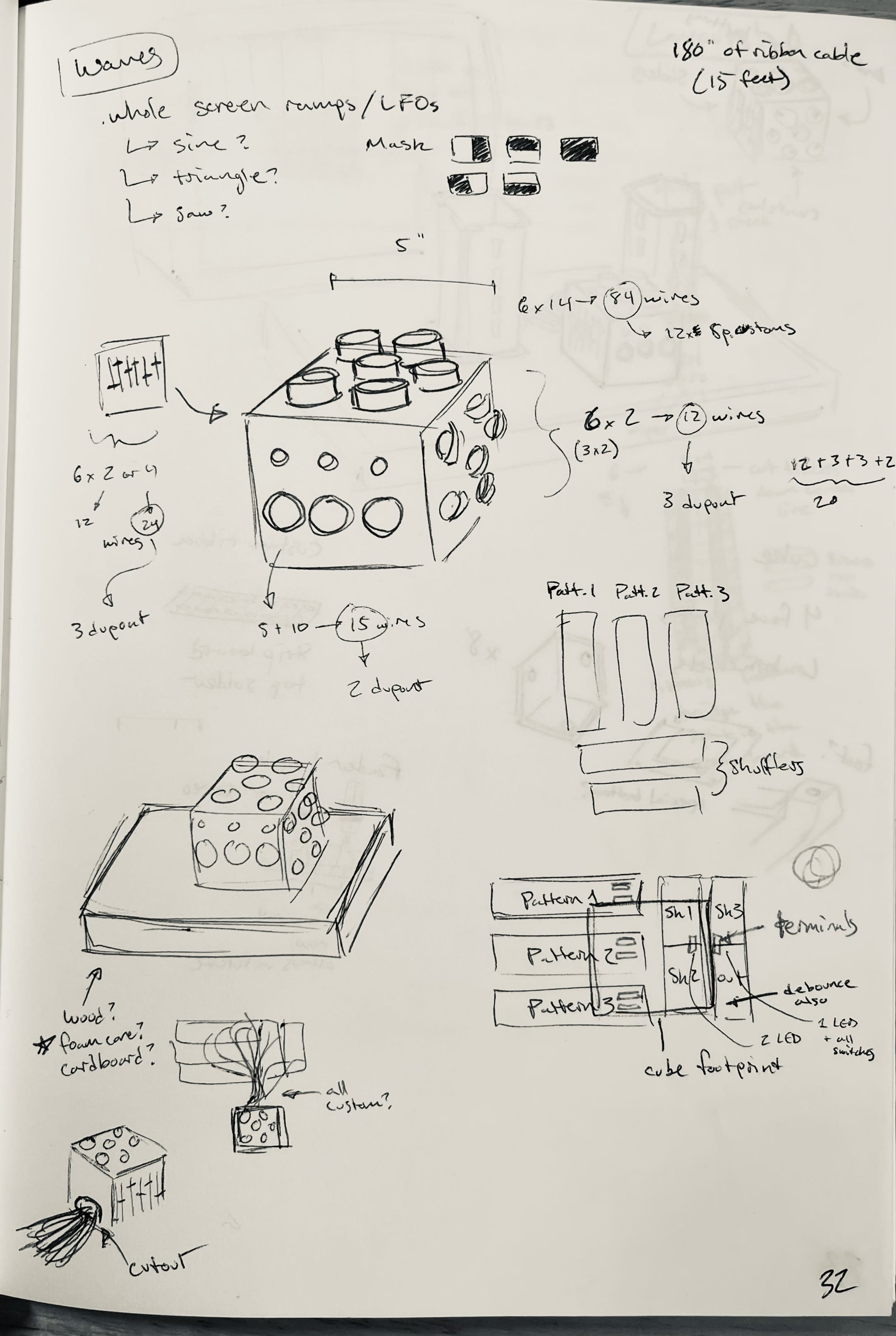
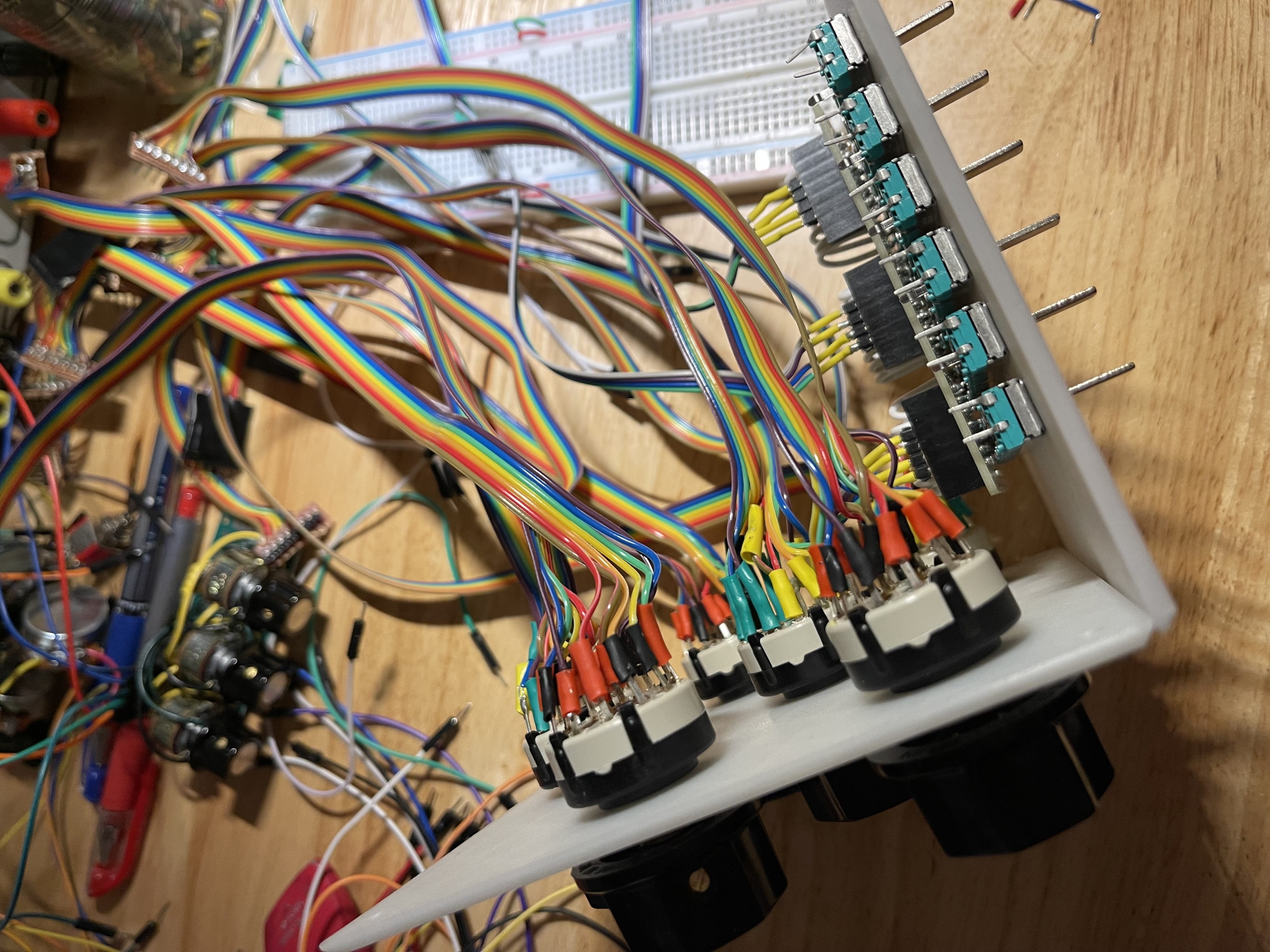
After a bit of sketching around, I decided to build a cube with nice flat panels on four sides, and an open back for the plentiful wiring that would have to extend from the interface to the pattern generators.
I wound up needing five full-size perma-proto boards to hold all the pattern generation circuitry, and since I was reusing the Sync Tower from my previous analog video synth, I decided to do the same trick and make brackets to stand those five boards upright into a second tower.
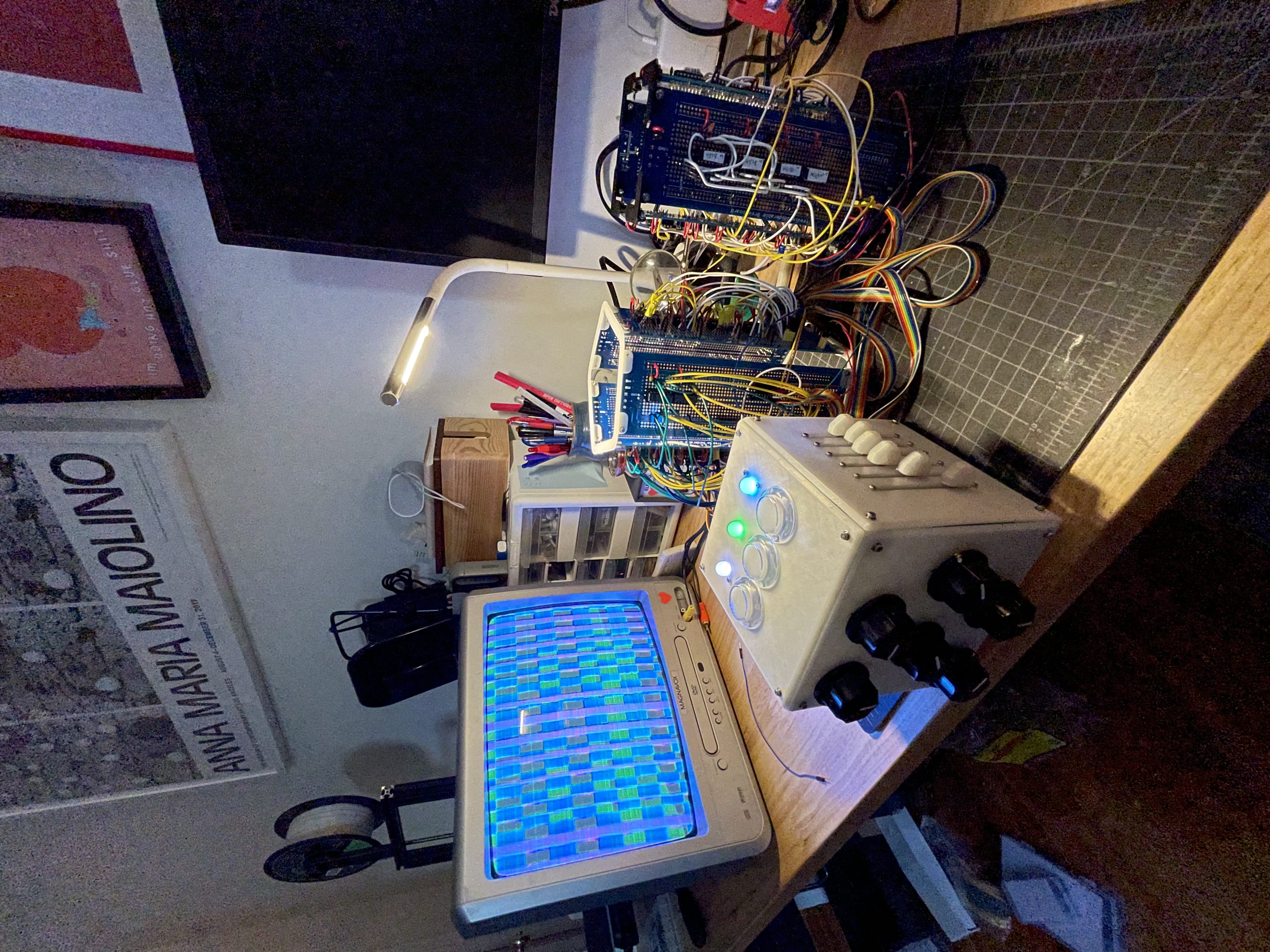
Both the Pattern Tower and the Sync Tower would stand behind the cube, putting the circuits on prominent display.
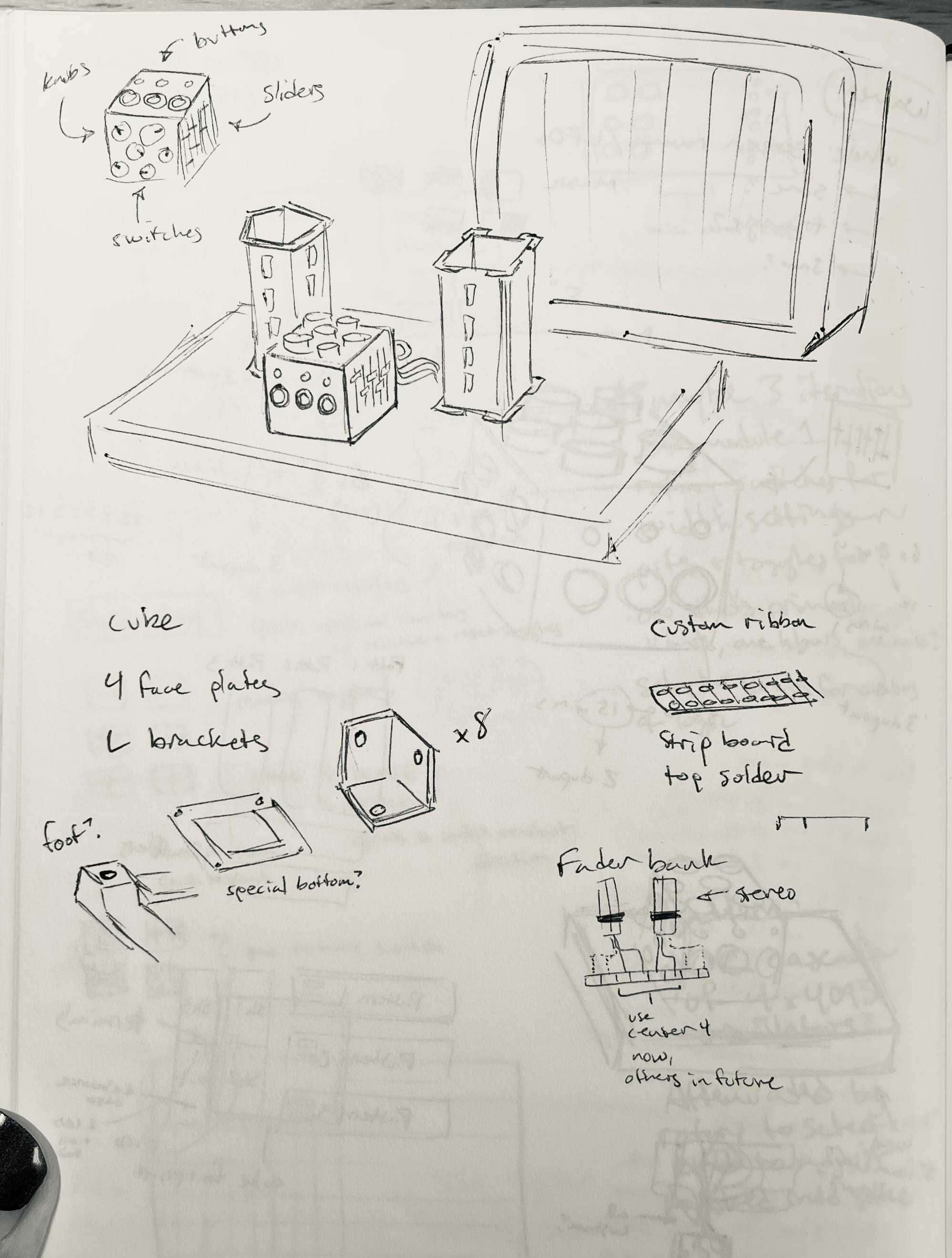
The contrast between the simple, opaque, white cube with friendly controls, and the messy rats-nest of wiring on the towers would also serve as a good indicator of what parts of the installation are meant to be touched.
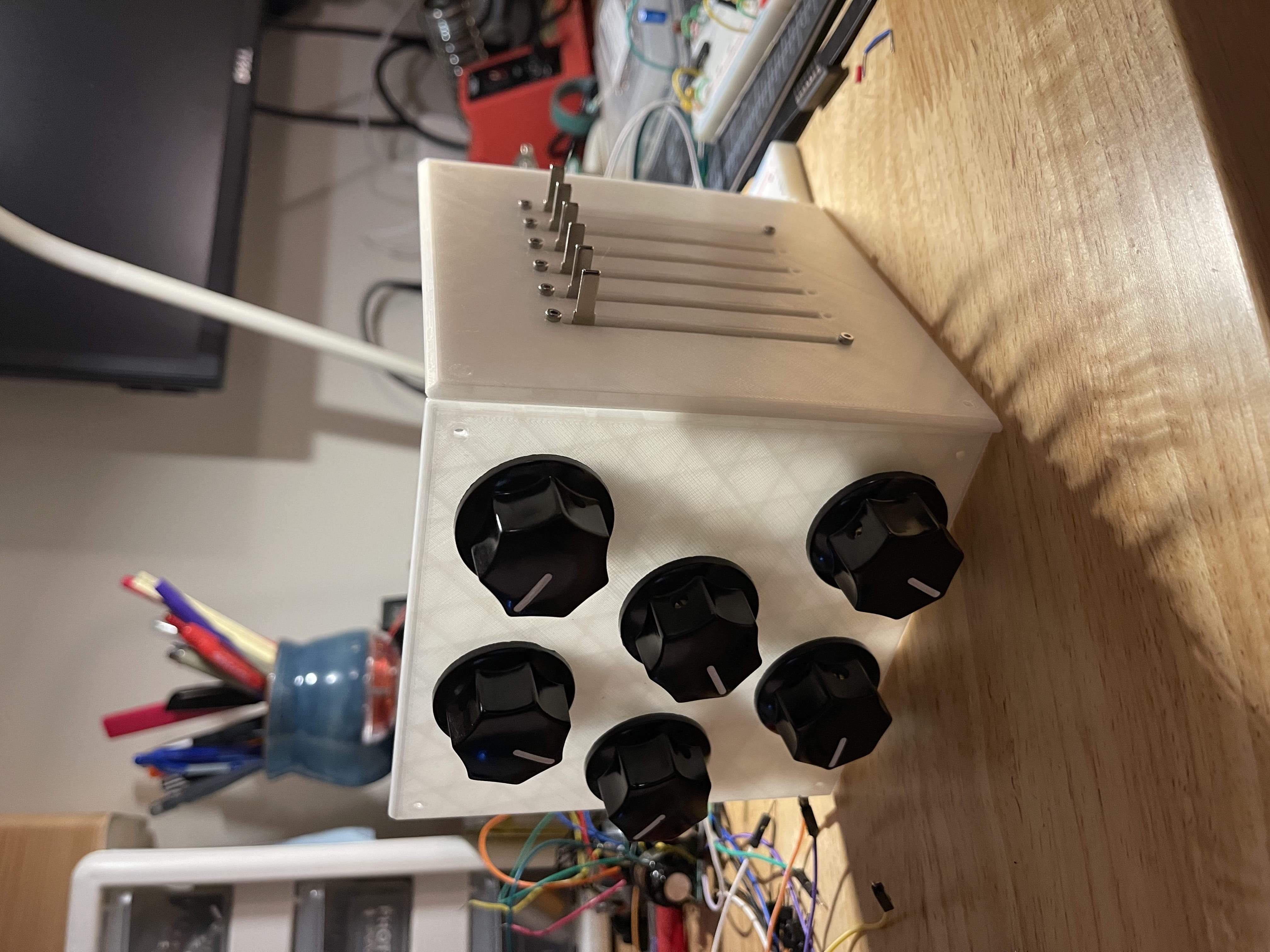
The cube itself would have four faces of controls. On top are the three buttons that control the color shuffler. On the left panel is a set of six rotary potentiometers, and on the right are six slide potentiometers. On the front panel are six rotary switches.
Part of the goal of this placement of controls is that it's not easy to look at all the controls at once, but it's easy to touch them. There are no labels to read, and even there were, it would be difficult to read them and understand the controls. This, I hoped, would also subtly reinforce the idea that you should be looking at the screen to understand what the controls do through experimentation, rather than having a manual to read. I wanted people to just get into it!
During the show itself, I stood nearby, ready to answer questions. Sometimes people would ask me "what does this knob do?" before trying anything and I would just shrug and say "only one way to find out I guess!". (If they wanted an actual explanation later I was happy to share, of course)
Building the enclosure
After some nerve-wracking 3D printing, I was ready to assemble. These flat panels would be joined together at the corners by little brackets I printed.
Even though the back was open, it was quite tricky to get all the brackets bolted in. Alas, this was before my discovery of heat-set inserts! Somehow we made it through.
Installation
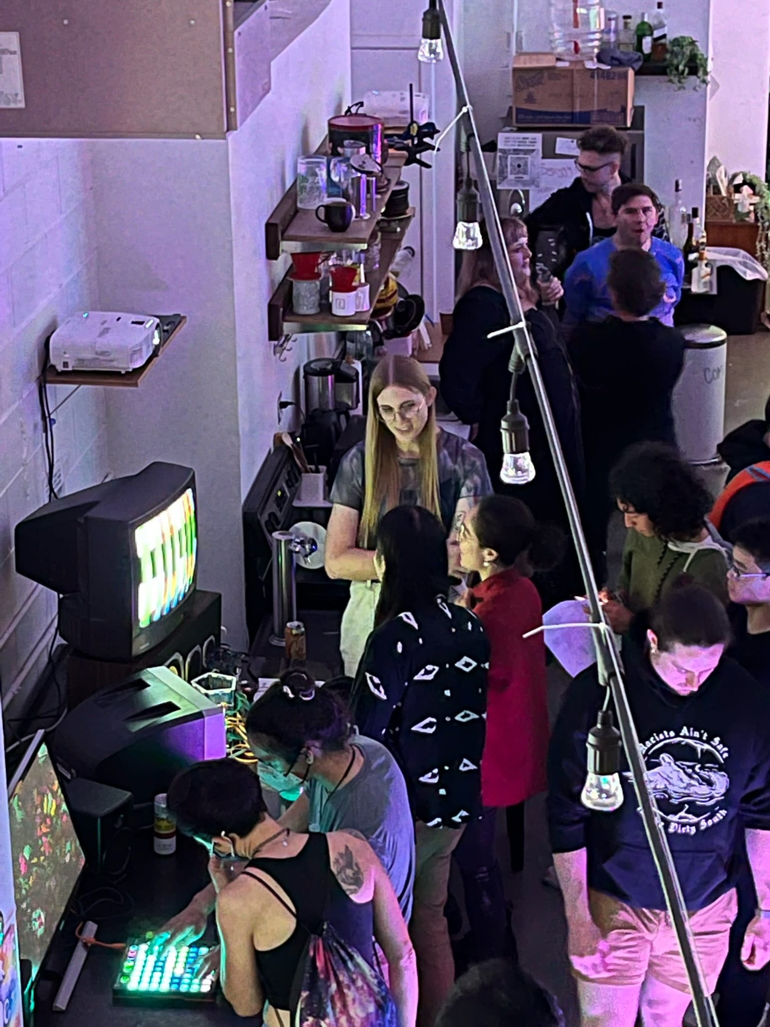
Machining the Ghost was an exhibition of interactive video art from about a dozen artists. There were truly amazing things on display, including a motion-reactive dancefloor, a dissected still-working VCR with tape loops drooling all over, a face-detecting webcam, a gigantic DIY modular analog rig... it was an honor to be a part of such a wonderful show!
Here's my station:
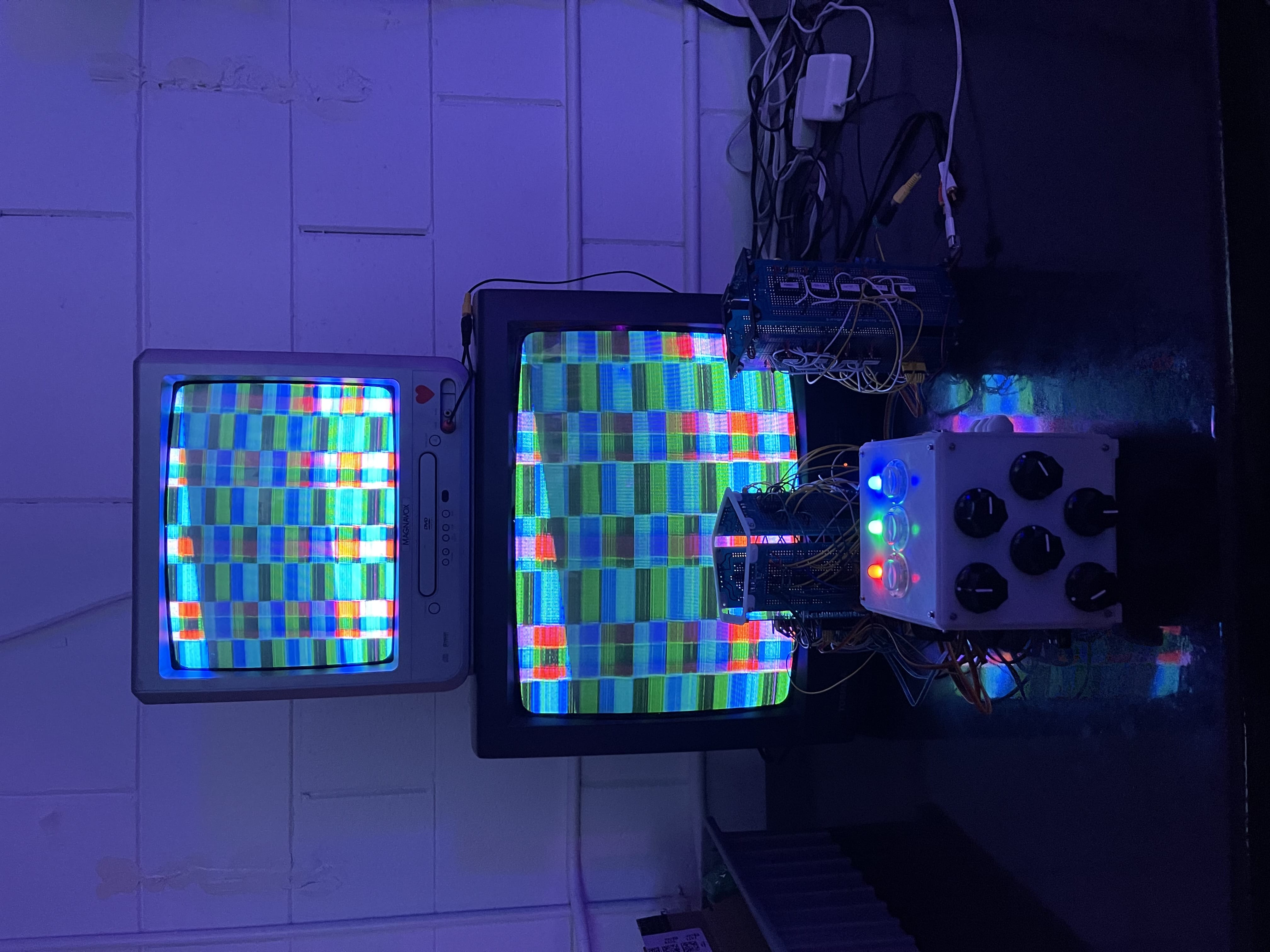
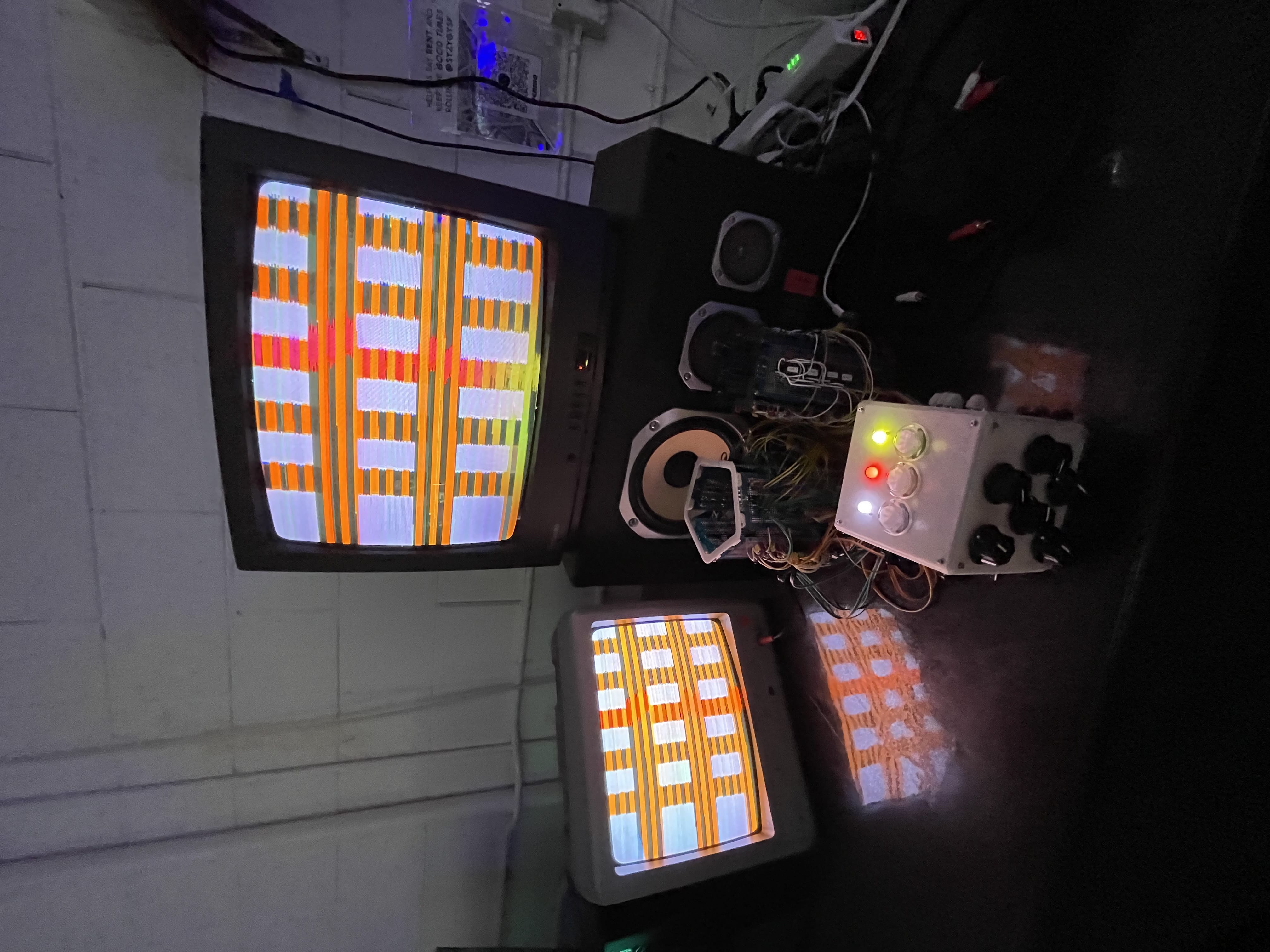
Nothing makes me happier than watching people play with things I built. Especially when I can help them experience the joy of a new artistic medium. I got a ton of visitors to my little setup, and a bunch of amazing questions about how TVs work.
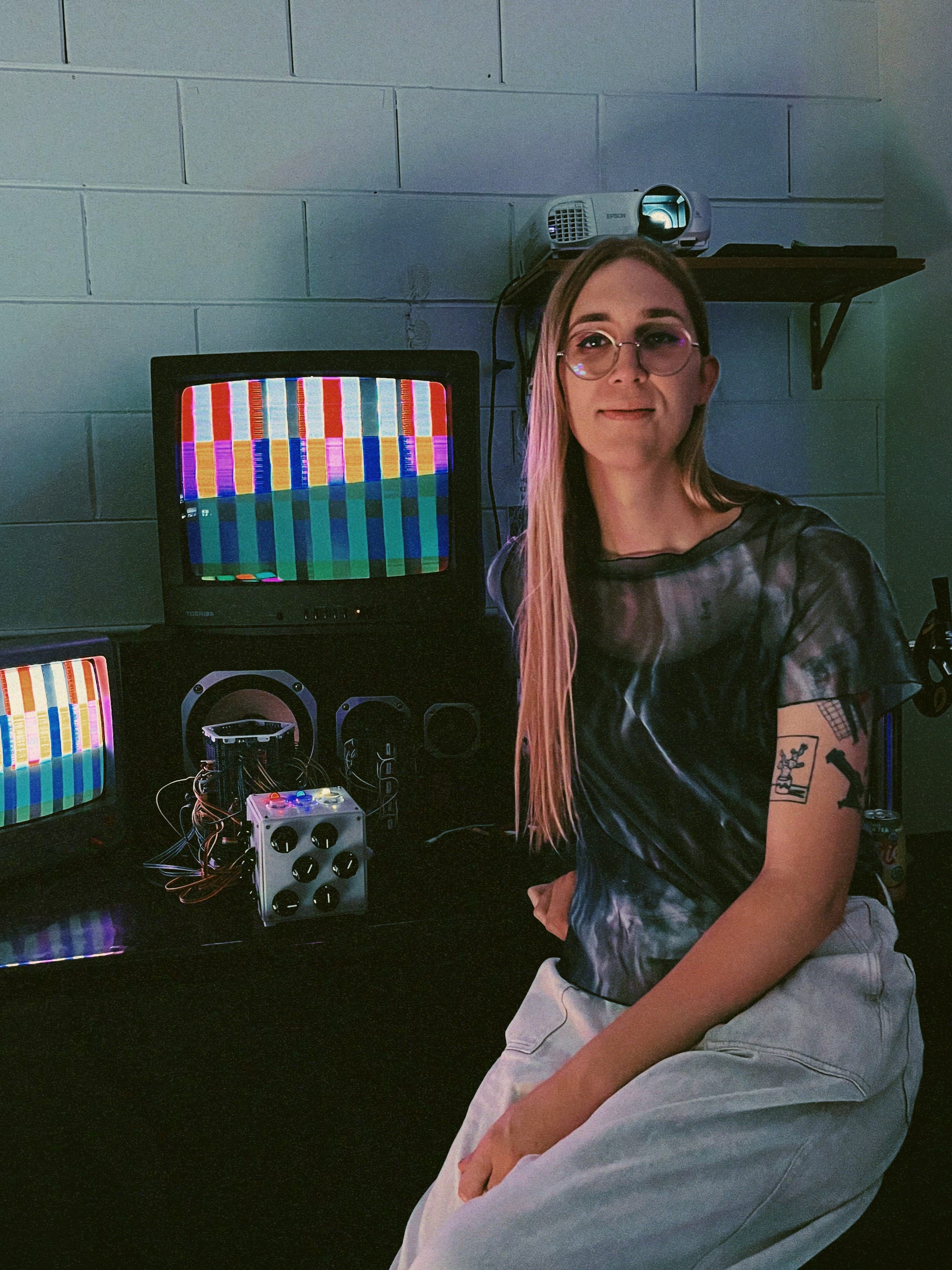
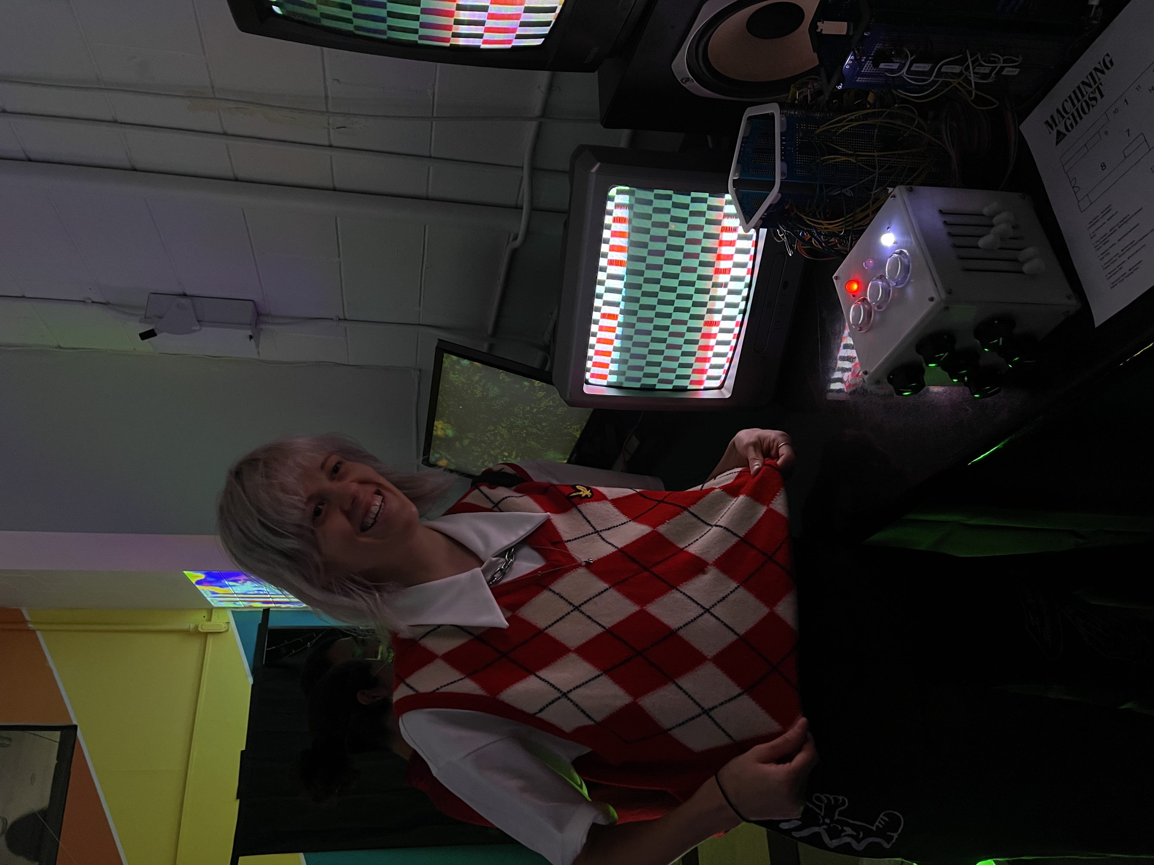
And people made such beautiful art with it! Here's a pic of my friend Anna making an homage to her sweater.
I'm very proud of this project. I hope to use it in a live performance setting some day! And I think ultimately, this takes me one step closer to building that analog video DJ deck… one day, one day.
Anyway, now I have a cool cube.
